

Electrical connector
- Summary
- Abstract
- Description
- Claims
- Application Information
AI Technical Summary
Benefits of technology
Problems solved by technology
Method used
Image

Examples
Embodiment Construction
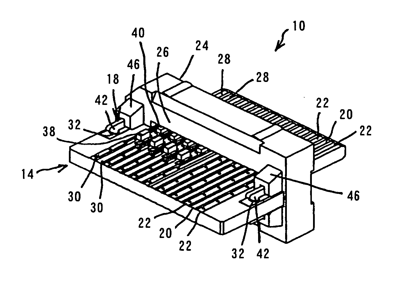
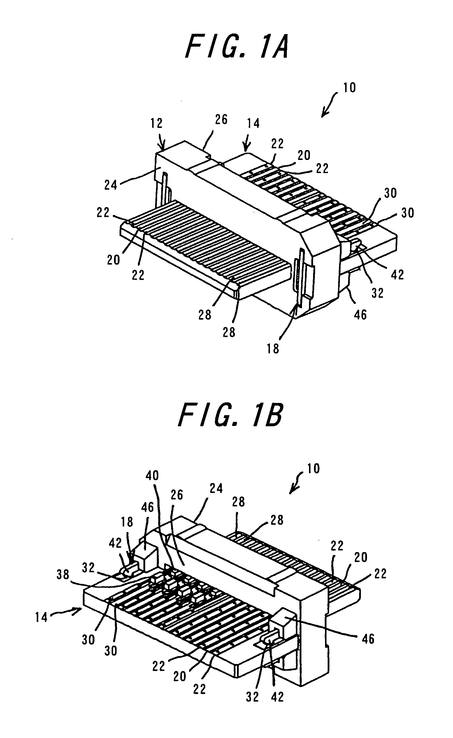
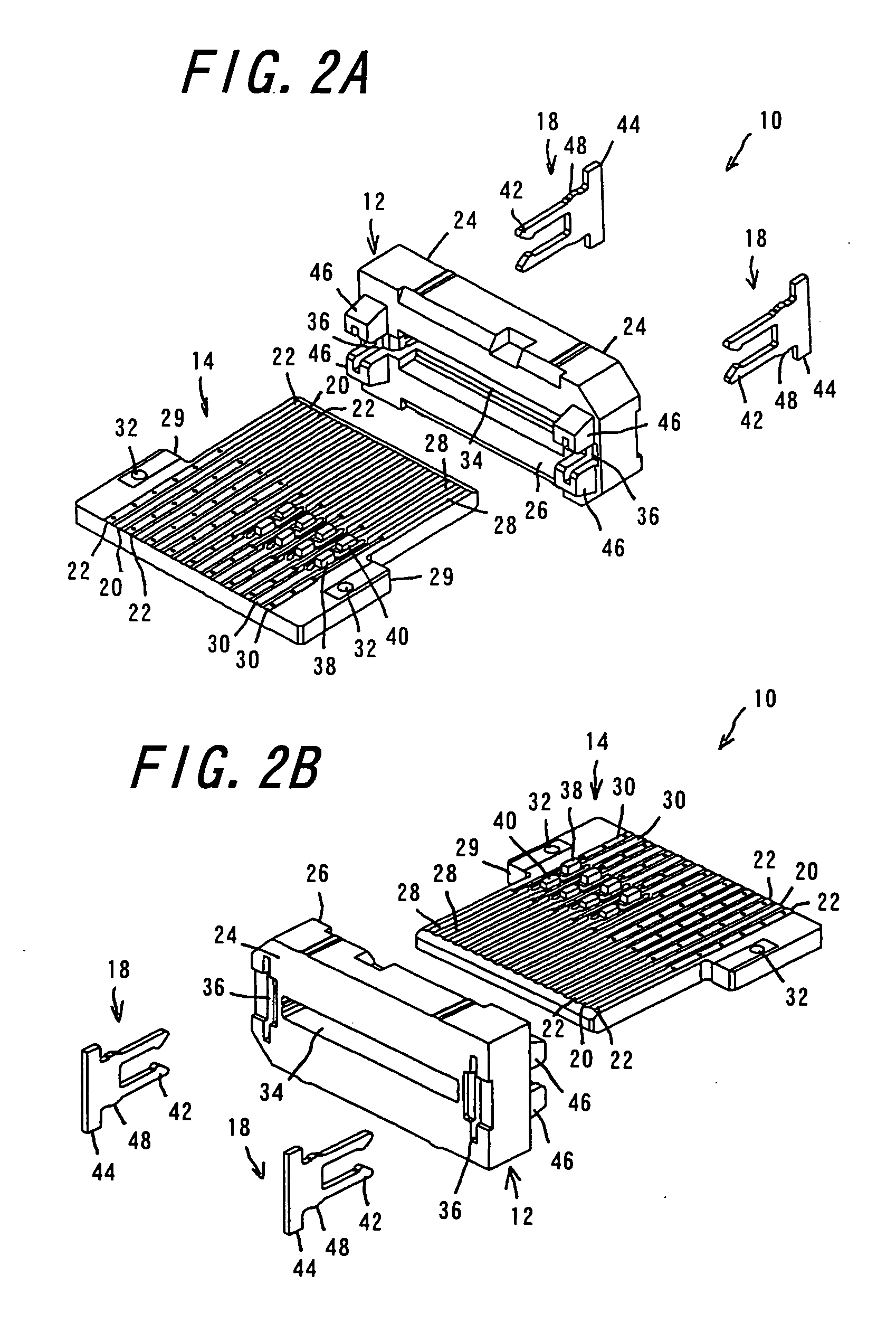
[0032] One embodiment of the electrical connector 10 according to the invention will be explained with reference to FIGS. 1A to 5B. FIG. 1A is a perspective view of the electrical connector according to the invention viewed from the fitting side, and FIG. 1B is a perspective view of the electrical connector according to the invention viewed from the connection portion side. FIG. 2A is an exploded perspective view of parts of the electrical connector viewed from the connection portion side, while FIG. 2B is an exploded perspective view of the parts of the electrical connector viewed from the fitting side. FIG. 3A is a perspective view of a substrate with capacitors and resistance chips mounted thereon viewed from the fitting side, and FIG. 3B is a perspective view of the substrate with the capacitors and resistance chips mounted thereon viewed from the connection portion side. FIG. 4 is a perspective view of a holding member. FIG. 5A is a perspective view of a housing viewed from the...
PUM
 Abstract
Description
Claims
Application Information