
Slide-and-lock stent

a technology of stent and stent body, which is applied in the field of expandable medical implants, can solve the problems of reducing the effective length of the stent in its deployment, affecting the treatment effect of patients, and inflicting abrasion trauma on the vessel walls,

Inactive Publication Date: 2007-02-08
REVA MEDICAL +1
View PDF99 Cites 51 Cited by
  • Summary
  • Abstract
  • Description
  • Claims
  • Application Information

AI Technical Summary

Benefits of technology

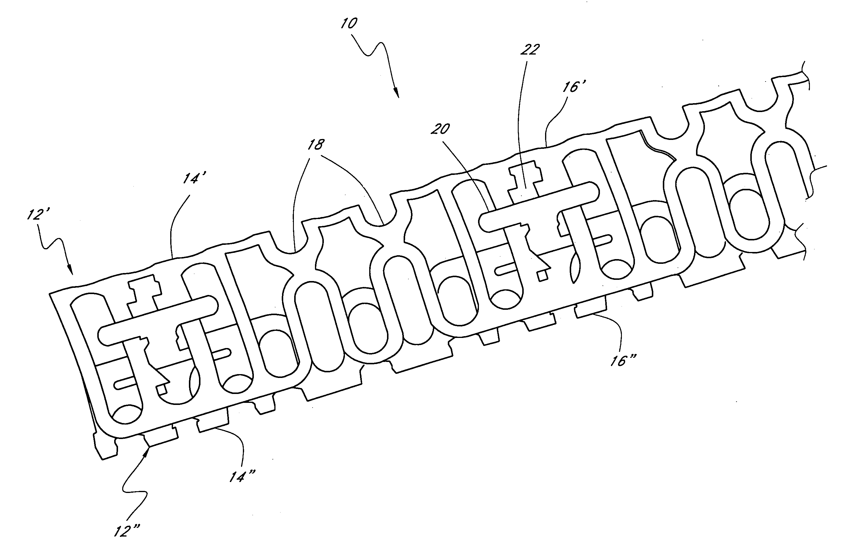
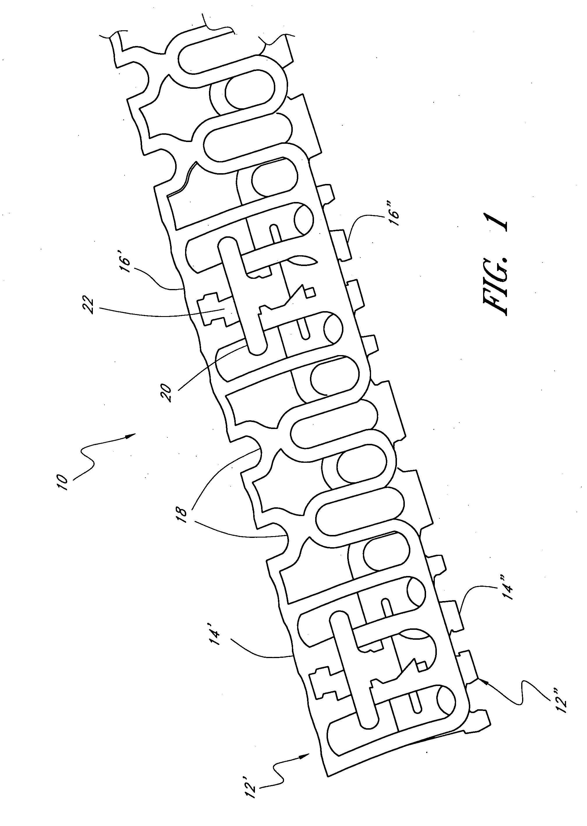
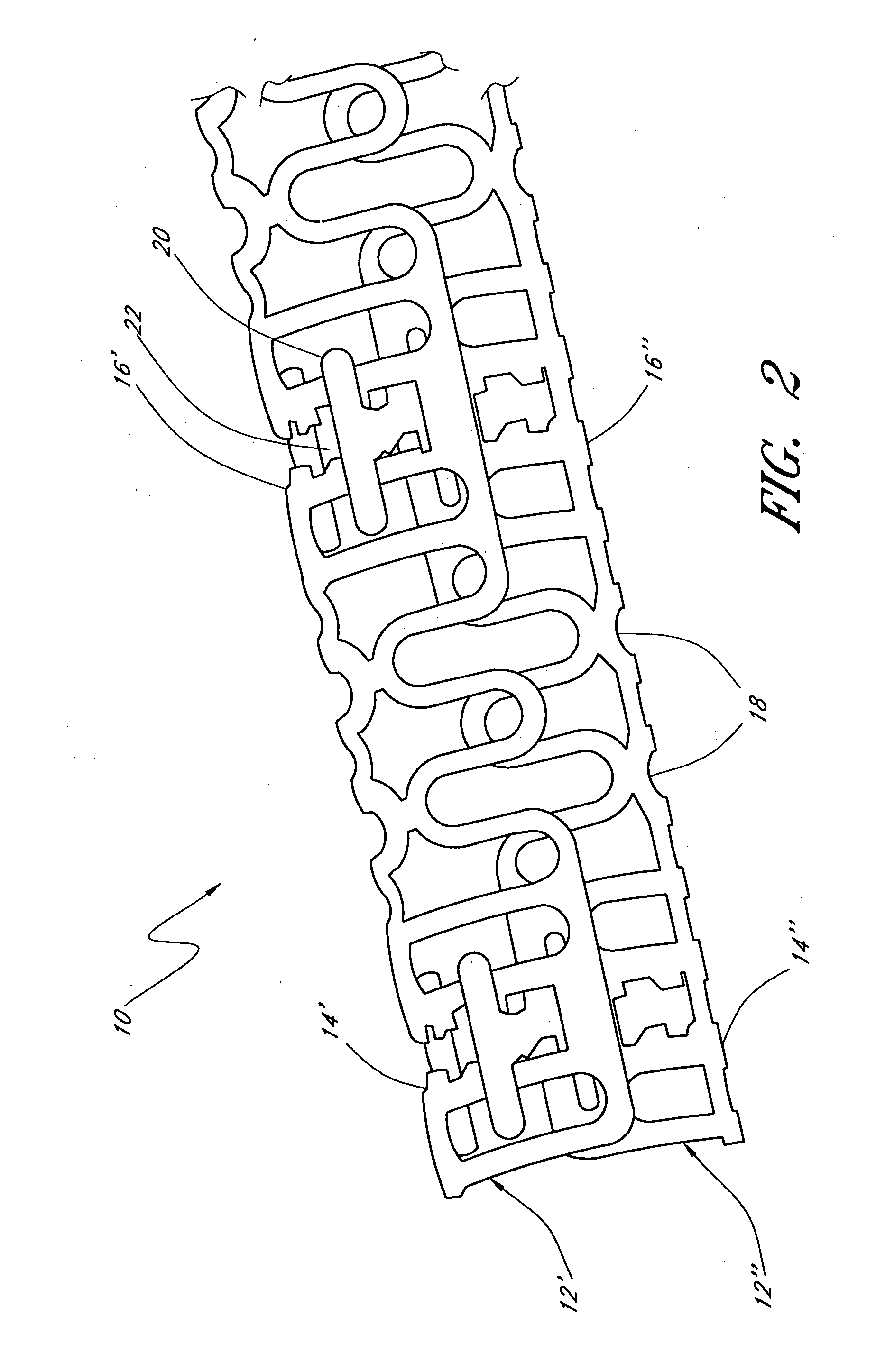
[0021] In one embodiment, a slide-and-lock stent is disclosed. The stent comprises a tubular member having longitudinal and circumferential axes. The tubular member comprises at least two circumferentially adjacent modules, each comprising at least two slide-and-lock radial elements which are separated from one another in the longitudinal axis by at least one passive radial element, wherein each slide-and-lock radial element comprises an engaging tab and a receiving slot which comprises a lockout tooth therein and defines a travel path. The engaging tabs from the slide-and-lock radial elements from each module are slidably engaged within receiving slots in the slide-and-lock radial elements from a circumferentially adjacent module, wherein the lockout tooth is configured to permit one-way sliding of the tabs along the travel path, such that the tubular member achieves expansion in the circumferential axis with reduced recoil as the circumferentially adjacent modules slide apart from one another.
[0024] In preferred variations to the slide-and-lock stent, the passive radial elements further comprise a tab and a slot, wherein tabs from the passive radial elements from each module are slidably engaged within slots in the passive radial elements from a circumferentially adjacent module. Preferably, at least one slot from the passive radial elements has a safety catch configured to stop the tab at a predetermined location so as to prevent further sliding of the tab within the slot.
[0031] In another preferred embodiment of the present invention, a slide-and-lock stent is disclosed comprising a tubular member having longitudinal and circumferential axes, wherein the tubular member comprises: a first radial element comprising an elongate rail comprising a deflectable tooth; and a second radial element, circumferentially adjacent to the first radial element, and comprising an engagement means configured to slidably engage the elongate rail of the first radial element and deflect the deflectable tooth as the tooth contacts the engagement means, such that the tubular member achieves expansion in the circumferential axis with reduced recoil.
[0035] In other preferred variations, the radial elements have deflectable teeth and a closed loop wherein the radial elements of the stent are uniquely configured to include tapered sections in the circumferential direction in order to reduce the radial thickness of the stent at the overlapping sections of circumferentially adjacent stent modules
[0041] In another preferred embodiment of the present invention, a slide-and-lock stent is disclosed comprising a tubular member having longitudinal and circumferential axes, wherein the tubular member comprises: a first module comprising at least two circumferentially offset slide-and-lock radial elements and a coupling element, wherein each radial element comprises a tab, a gap comprising lockout teeth, and a slot; and a second module configured substantially identical to the first module and circumferentially adjacent to the first module, wherein the radial elements from the second module are slidably engaged within the slots of the corresponding radial elements from the first module, and wherein the tabs of the radial elements from the second module are slidably engaged within the gaps of the corresponding radial elements from the first module, such that the lockout teeth engage the tabs to minimize recoil.

Problems solved by technology

Another problem inherent in many prior art stent configurations is the longitudinal contraction that such structures typically undergo as they are radially expanded.
This not only reduces the effective length of the stent in its deployed state but may cause abrasion trauma to be inflicted on the vessel walls during expansion.
The use of wire has a number of disadvantages associated therewith including for example, its substantially constant cross-section which may cause greater or lesser than an ideal amount of material to be concentrated at certain locations along the stent.
Additionally, wire has limitations with respect to the shapes it can be formed into thus limiting the expansion ratio, coverage area, flexibility and strength that can ultimately be attained therewith.
Unfortunately, the circumferential elements have free ends, protruding from the paired slots.
Both the free ends and the stand off may pose significant risks of thrombosis and / or-restenosis.
Moreover, this stent design would tend to be rather inflexible as a result of the plurality of longitudinal backbones.
The disadvantage of these designs is that they tend to exhibit very poor longitudinal flexibility.
However, these coupled rolls lack vessel support between adjacent rolls.
Furthermore, these designs exhibit extensive overlapping of stent elements in multiple layers, which makes the delivery profile rather thick.
Although balloon expandable stents are the first stent type to be widely used in clinical applications, it is well recognized that balloon expandable stents have a variety of shortcomings which may limit their effectiveness in many important applications.
This is disadvantageous because it has been found that over-inflation may damage the blood vessel.
Furthermore, a deployed balloon expandable stent may exhibit chronic recoil over time, thereby reducing the patency of the lumen.
Still further, balloon expandable stents often exhibit foreshortening (i.e., a reduction in length) during expansion, thereby creating undesirable stresses along the vessel wall and making stent placement less precise.
Still further, many balloon expandable stents, such as the original Palmaz-Schatz stent and later variations, are configured with an expandable mesh having relatively jagged terminal prongs, which increases the risk of injury to the vessel, thrombosis and / or restenosis.
However, this type of stent utilizes the application of heat to produce expansion of the stent structure.
However, heat expandable stents have not gained widespread popularity due to the complexity of the devices, unreliable expansion properties and difficulties in maintaining the stent in its expanded state.
Still further, it has been found that the application of heat during stent deployment may damage the blood vessel.
In summary, although a wide variety of stents have been proposed over the years for maintaining the patency of a body lumen, none of the existing schemes has been capable of overcoming most or all of the above described shortcomings.

Method used


Image

  • Slide-and-lock stent
  • Slide-and-lock stent
  • Slide-and-lock stent

Examples


embodiment 300

[0164] In yet another alternative embodiment, it will be appreciated that deflectable teeth may be used, rather than deflectable rails or members, to provide the locking mechanism that facilitates mono-directional expansion. For example, FIG. 25 illustrates a portion of another stent embodiment 300 wherein two radial elements 300(1), 300(2) are slidably interconnected. Each radial element is provided with a rail 308 having a plurality of deflectable teeth 306. Similar radial elements may be coupled via flexible linkage elements 310, 312 to provide a stent having a desired axial length. In this embodiment, the engagement means comprise locking tabs 302, 304 which are configured to slide circumferentially within elongate slots surrounding the rail, and to slide along the sides of the deflectable teeth 306. Each of the teeth is sufficiently flexible such that the teeth may deform inward toward the rail 308 (i.e., within the plane of the radial element) for allowing the locking tabs 302...

embodiment 320

[0165] With reference now to FIG. 26, a portion of another preferred stent embodiment 320 is illustrated wherein radial elements 320(1), 320(2) are slidably interconnected. Similar to the embodiment just described, each radial element is provided with a rail 328 having a plurality of deflectable teeth 326. However, in this embodiment, each of the teeth is angled upward and is configured to deflect downward (i.e., in a radial direction), rather than inward toward the rail as discussed with respect to FIG. 25. As the locking tabs 322, 324 slide along the deflectable teeth 326, the teeth are caused to deflect downward for allowing the tabs 322, 324 to pass over the teeth 326 during deployment. However, due to the angle of the teeth, the locking tabs may only move in one direction. More particularly, if a compressive force pushes the radial elements 320(1), 320(2) back toward the collapsed condition, the locking tabs 322, 324 will abut against the teeth 326, thereby preventing further r...

embodiment 340

[0181] With reference now to FIG. 31, a portion of another stent embodiment 340 is illustrated wherein radial elements 340(1), 340(2) are slidably interconnected. Each radial element is provided with an outer surface formed, at least in part, with a series of serrations or ridges. More particularly, the surfaces comprise a series of valleys 344 and ridges 346. In the illustrated configuration, a locking tab 342 of radial element 340(2) slides along the surface of radial element 340(1). The locking tab 342 is formed with a thin neck portion 350 and a wider head portion 352. The neck portion 350 is configured for allowing the head 352 to deflect outward in a radial direction. The shape of the valleys 344 and ridges 346 allows the head 352 of the locking tab 342 to ratchet along the surface of the adjacent element in only one direction, thereby providing a locking means to maintain the stent in the expanded condition. Although the ridges and valleys are only necessary along the region ...


PUM


Abstract

The invention relates to an expandable stent comprising circumferentially adjacent modules. The modules comprise longitudinally adjacent slide-and-lock radial elements which permit one-way sliding of the radial elements from a collapsed diameter to an expanded / deployed diameter, but inhibit radial recoil from the expanded diameter.

Description

CROSS-REFERENCE TO RELATED APPLICATIONS [0001] This application is a continuation-in-part of U.S. patent application Ser. No. 11 / 016,269 filed on Dec. 17, 2004, and claims priority thereto under 35 U.S.C. §120.BACKGROUND OF THE INVENTION [0002] 1. Field of the Invention [0003] The invention relates to expandable medical implants for maintaining support of a body lumen. [0004] 2. Description of the Related Art [0005] Stents or expandable grafts are implanted in a variety of body lumens in an effort to maintain their patency. These devices are typically intraluminally implanted by use of a catheter, which is inserted at an easily accessible location and then advanced to the deployment site. The stent is initially in a radially compressed or collapsed state to enable it to be maneuvered through the lumen. Once in position, the stent is deployed which, depending on its configuration, may be achieved either automatically or manually, by for example, the inflation of a balloon about which...

Claims


Application Information

Patent Timeline
Patent Type & Authority Applications(United States)
IPC IPC(8): A61F2/06A61F2/92
CPCA61F2/92A61F2/82A61F2220/0058A61F2220/005A61F2210/0076A61F2/93B33Y80/00
Inventor SCHMID, ERICMORRIS, ANDREWNGUYEN, JOHN D.
Owner REVA MEDICAL
Learn More