Processing method for brake rotor-equipped wheel bearing devices

a technology of brake rotor and processing method, which is applied in the direction of manufacturing tools, transportation and packaging, portable lathes, etc., can solve the problems of reducing the accuracy of surface runout and the inability to suppress the surface so as to reduce the rotation runout of the pad slide surfaces of the brake rotor and the processing accuracy is high. , the effect of suppressing the surface runou

Active Publication Date: 2007-02-15
NTN CORP
View PDF11 Cites 12 Cited by
  • Summary
  • Abstract
  • Description
  • Claims
  • Application Information

AI Technical Summary

Benefits of technology

[0008] An object of this invention is to provide a method capable of cutting the pad slide surfaces of the brake rotor of a brake rotor-equipped wheel bearing device efficiently with higher accuracy.
[0015] By lathing the pad slide surfaces of the brake rotor with the reference provided by the wheel pilot end surface of the hub ring, it becomes possible to attain a high accuracy processing which suppresses the surface runout of the pad slide surfaces of the brake rotor without restraining the outer member. To give a concrete example, the surface runout of the pad slide surfaces of the brake rotor can be made not more than 30 μm. Therefore, according to this invention, since the rotation runout of the pad slide surfaces of the brake rotor can be minimized, it is possible to improve the rotation accuracy of the brake rotor put in its mounted state and suppress the occurrence of the brake shudder during braking.

Problems solved by technology

Even if the processing accuracy is increased, however, not only does the processing errors on the parts accumulate during assembly of the wheel bearing device, but also assembling errors are produced, thus making it impossible to suppress the surface runout of the pad slide surfaces of the brake rotor.
The deformation of the rolling element contact surface during cutting load application causes the runout in the bearing rotation axis and the processing axis, resulting in the corresponding degradation of the surface runout accuracy.

Method used


Image

  • Processing method for brake rotor-equipped wheel bearing devices
  • Processing method for brake rotor-equipped wheel bearing devices
  • Processing method for brake rotor-equipped wheel bearing devices

Examples


first embodiment

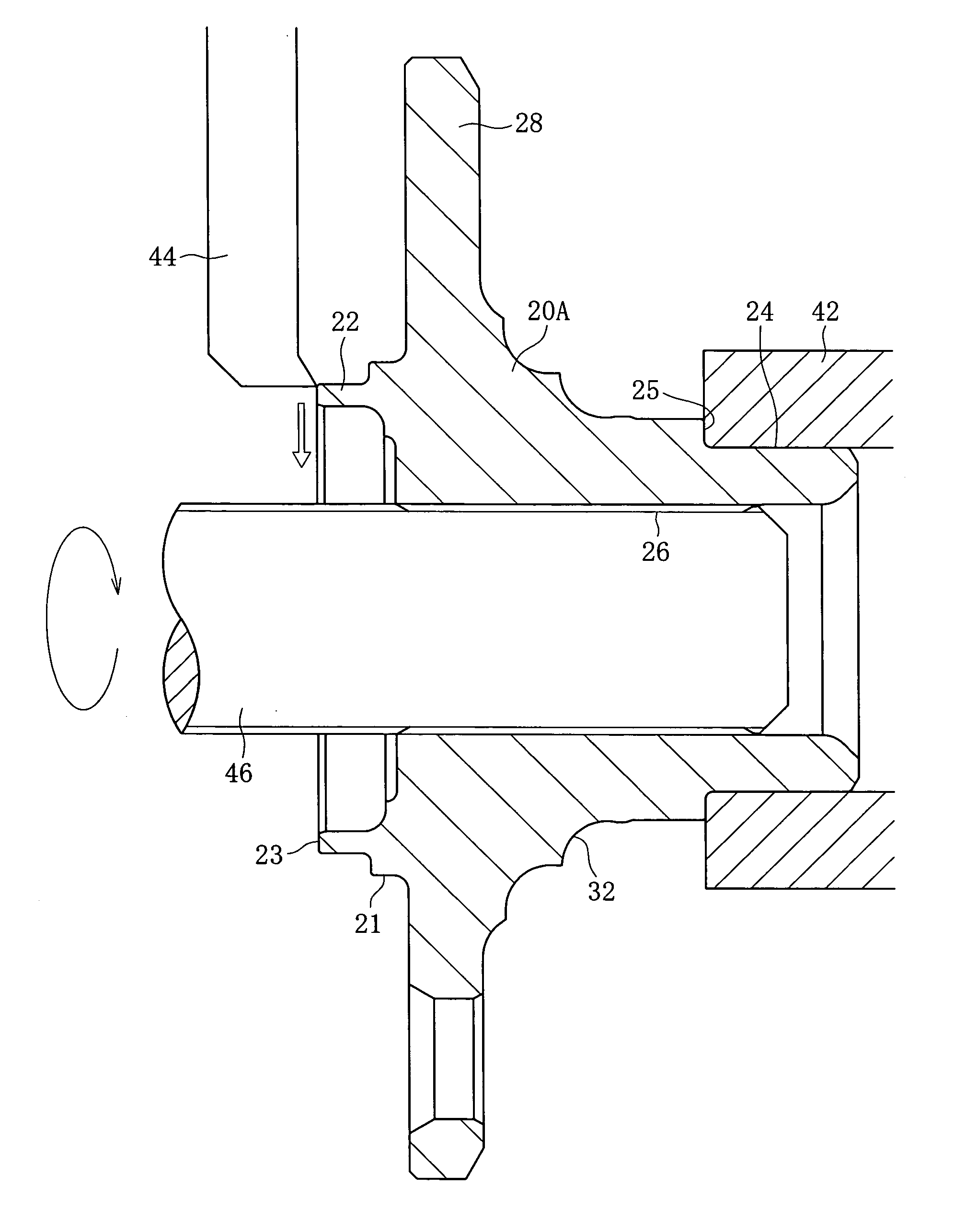
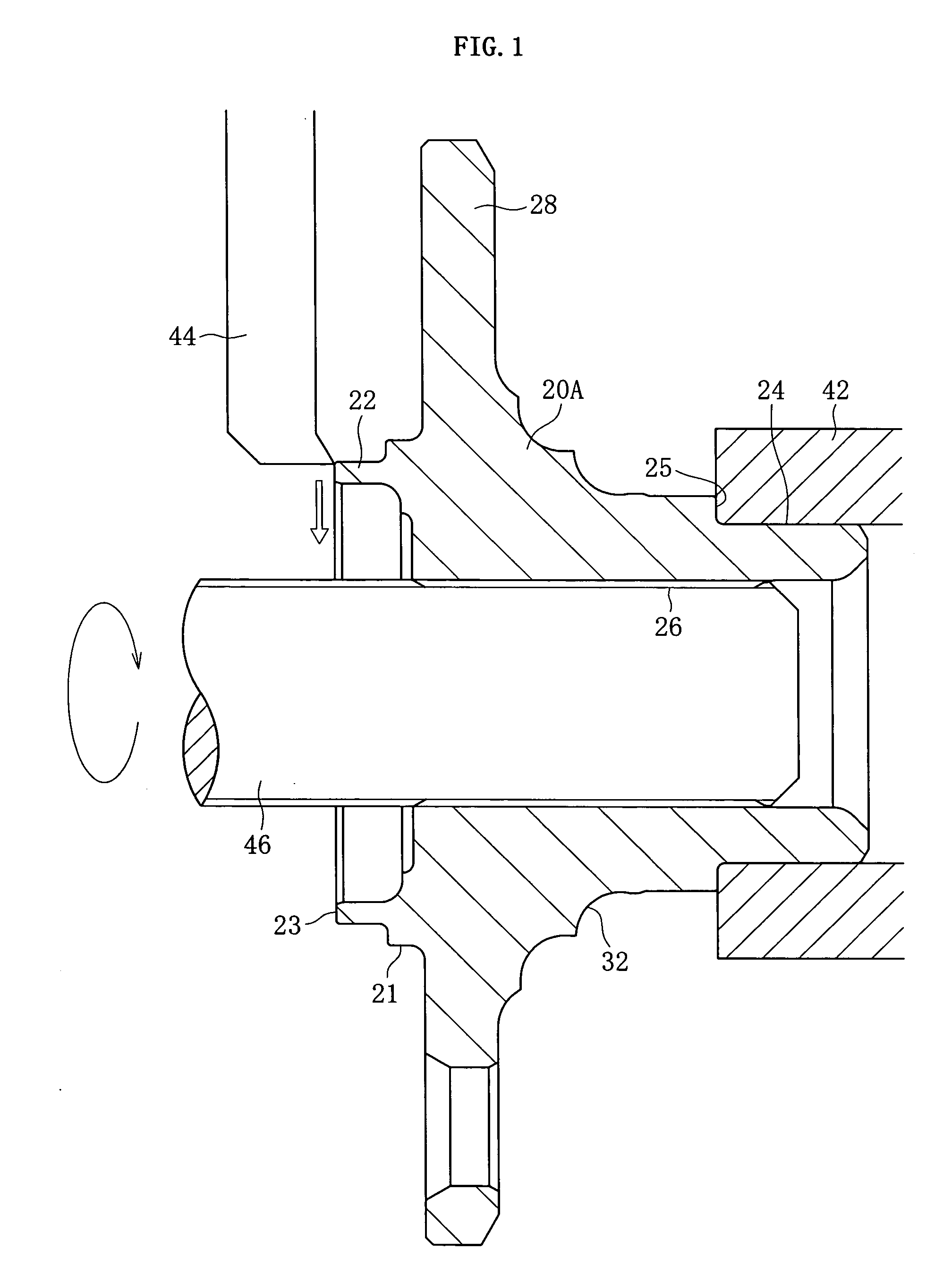
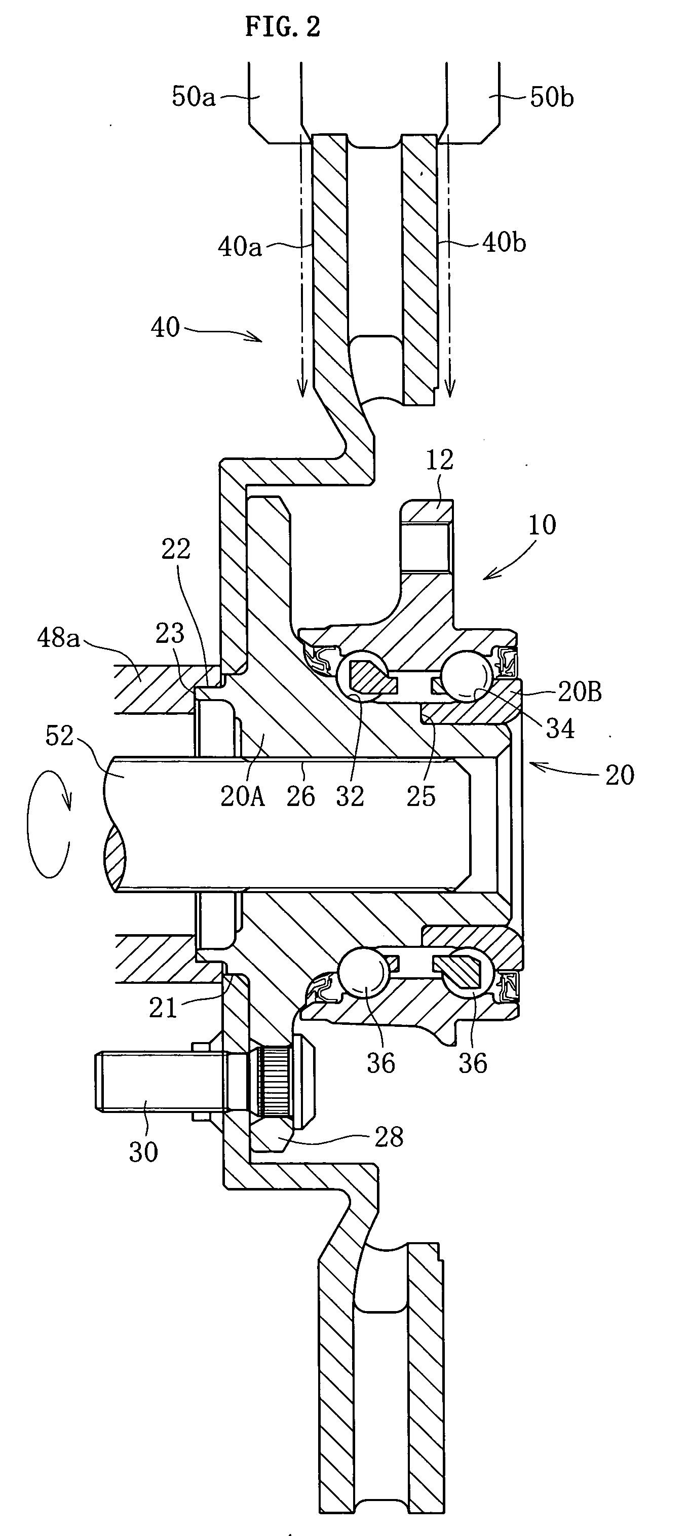
[0039] Next, a description will be given of the method for processing the pad slide surfaces 40a and 40b of the brake rotor 40 in the brake rotor-equipped wheel bearing device. The processing method in the first embodiment consists of a first step and a second step. In the first step, with the hub ring 20A present singly, the end surface 23 of the wheel pilot 22 of the hub ring 20A is lathed with the reference provided by the inner ring abutment surface 25. In the second step, with the bearing put in its assembled state, after the brake rotor is attached, the outer diameter of the wheel pilot 22 of the hub ring 20A is chucked, and the pad slide surfaces 40a and 40b of the brake rotor 40 are lathed with the reference provided by the wheel pilot end surface 23.

[0040] The first step will be described with reference to FIG. 1. The hub ring 20A constituting the inner member 20 of the wheel bearing device is held at the small diameter section 24 by a chuck device 42. At this time, the chu...

second embodiment

[0046] The second embodiment is such that, as shown in FIG. 8, with the hub ring 20A present singly, the outer peripheral surface of the hub ring 20A is ground with the reference provided by the end surface 23 of the wheel pilot 22. In this case, the end surface of the wheel pilot 22 is supported by the chuck device 54, and use is made of a formed grinding stone 56 having a contour corresponding to the outer peripheral surface of the hub ring 20A including at least the raceway 32, inner ring abutment surface 25, and small diameter sections 24.

[0047] In addition, the wheel bearing device has been described so far by taking as an example one for driving wheels formed with the spline hole 26 in the inner member 20 (hub ring 20A); however, the wheel bearing device may be such that it is used for non-driving wheels and such that the hub ring 20A is solid.

third embodiment

[0048] Next, this invention will be described with reference to FIGS. 10 through 16. It consists of a first step and a second step. In the first step, the end surface 23 of the wheel pilot 22 of the hub ring 20A is lathed in a bearing ASSY state (FIG. 10), and in the second step, the pad slide surfaces 40a and 40b of the brake rotor 40 are lathed (FIG. 11).

[0049] The first step will be described with reference to FIG. 10. The outer diameter of the knuckle pilot 16 of the outer member 10 of the wheel bearing device is held by the chuck device 42. And, the serration shaft of the work carry 46 is inserted in the serration hole 26 in the hub ring 20A, and the work carry 46 is rotated as indicated by an arrow, thus imparting a torque so that the hub ring 20A will rotate around the rotation center of the wheel bearing device. And, the turning tool 44 is fed as indicated by an arrow in white to lathe the end surface 23 of the wheel pilot 22. Irrespective of dimensional errors or assembly e...


PUM

PropertyMeasurementUnit
diameteraaaaaaaaaa
outer diameteraaaaaaaaaa
inner diameteraaaaaaaaaa

Abstract

An outer member 10 and an inner member 20 constituting a wheel bearing device are assembled and the brake rotor 40 is fixed to the hub ring 20A of the inner member. In this state, the pad slide surfaces 40a and 40b of the brake rotor 40 are lathed with the reference provided by a wheel pilot end surface 23. Alternatively, the wheel pilot end surface 23 of the hub ring 20A by chucking the knuckle pilot 16 of the outer member 10 with the wheel bearing device put in its assembled state, and the pad slide surfaces 40a and 40b of the brake rotor 40 are lathed with the reference provided by the wheel pilot end surface 23.

Description

BACKGROUND OF THE INVENTION [0001] 1. Field of the Invention [0002] This invention relates to a processing method for brake rotor-equipped wheel bearing devices, and more particularly it relates to a method for cutting the pad slide surfaces of a brake rotor. [0003] 2. Brief Description of the Prior Art [0004] Wheel bearing devices for automobiles are used for driving wheels and non-driving wheels. At any rate, in wheel bearing devices, the surface runout of the brake surfaces, i.e., the pad slide surfaces, during rotation of the brake rotor, becomes a cause of brake shudder during braking, so that high processing accuracy and high dimensional accuracy are required of the parts of the wheel bearing device. Even if the processing accuracy is increased, however, not only does the processing errors on the parts accumulate during assembly of the wheel bearing device, but also assembling errors are produced, thus making it impossible to suppress the surface runout of the pad slide surfac...

Claims


Application Information

Patent Timeline
Patent Type & Authority Applications(United States)
IPC IPC(8): B23P15/18
CPCB23B5/02Y10T29/53648B60B27/0026B60B27/0094B23P15/003Y10T82/10Y10T82/2585Y10T82/21Y10T29/49536Y10T409/303808Y10T409/304424Y10T29/49995Y10T29/49696Y10T29/4984B60B27/0005Y10T29/49535
Inventor SHIBATA, KIYOTAKEYAMAMOTO, KAZUNARISHIGEOKA, KAZUHISANISHIKI, TAKUKOMORI, KAZUOMAEDA, TAKAO
Owner NTN CORP
Why Eureka
Try Eureka