
Piezooscillator

a crystal oscillator and oscillator technology, applied in piezoelectric/electrostrictive/magnetostrictive devices, piezoelectric/electrostriction/magnetostriction machines, electrical equipment, etc., can solve the problem of increased man-hour, possible cause of frequency difference not meeting the specification, and the crystal oscillator suffering a shock applied from outside, so as to improve the shock resistance of the crystal oscillator

Inactive Publication Date: 2007-02-15
NIHON DEMPA KOGYO CO LTD
View PDF2 Cites 25 Cited by
  • Summary
  • Abstract
  • Description
  • Claims
  • Application Information

AI Technical Summary

Benefits of technology

[0008] The present invention has been made under such circumstances, and an object thereof is to provide, for a piezooscillator having a piezoelectric resonator, the piezooscillator having a superior shock-resistance.
[0010] Another piezooscillator according to the present invention is a piezooscillator having a piezoelectric resonator comprises: a case surrounding a space in which the piezoelectric resonator is provided and including a first substrate and a cover; a second substrate mounting the piezoelectric resonator thereon; a buffer material supporting the second substrate and suppressing a shock conveyed from the case to the piezoelectric resonator; and a wiring member electrically connecting the first substrate and the second substrate and having flexibility.
[0011] Further, still another piezooscillator according to the present invention is a piezooscillator having a piezoelectric resonator, comprises: a case surrounding a space in which the piezoelectric resonator is provided and including a first substrate and a cover; a second substrate mounting the piezoelectric resonator thereon; a buffer material supporting the piezoelectric resonator and suppressing a shock conveyed from the case to the piezoelectric resonator; and a wiring member electrically connecting the first substrate and the second substrate and having flexibility.
[0013] According to the piezooscillator of the present invention, the piezoelectric resonator is supported by the buffer material in the case having the substrate and the cover, hence, when the shock is applied to the case from outside, the shock is absorbed by the buffer material to be eased and problems such as a variation in the frequency or the oscillation stop of the piezooscillator can be prevented, so that the piezooscillator can be improved in shock-resistance.

Problems solved by technology

Meanwhile, the crystal oscillator is used in electronic equipment such as mobile communication equipment and transmission communication equipment or in a base station as a high-precision reference oscillation source, however, when transporting the crystal oscillator, or when installing the crystal oscillator into the electronic equipment or the base station, there is a threat for the crystal oscillator of suffering a shock applied from outside and, for example, when the crystal oscillator in FIGS.
Further, even though a positional difference of the crystal piece is small, when a high-precise frequency is required to be set, a frequency difference not meeting the specification is possibly caused.
The shock-resistance of the crystal resonator is affected by the size, shape and thickness of the crystal piece and the shape of a support member supporting the crystal piece, therefore, the shock-resistance is conventionally improved by contriving the structure of the crystal resonator, however, the structure is made complicated due to the easily-broken crystal piece and the downsizing of the crystal resonator, so that a man-hour is increased and productivity is degraded, and further the downsizing is caused to be prevented.

Method used


Image

  • Piezooscillator
  • Piezooscillator
  • Piezooscillator

Examples


Embodiment Construction

)

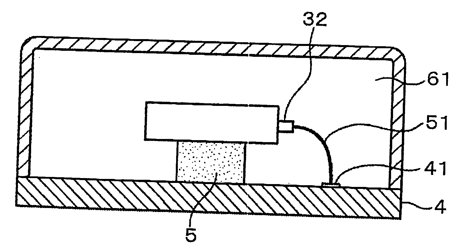
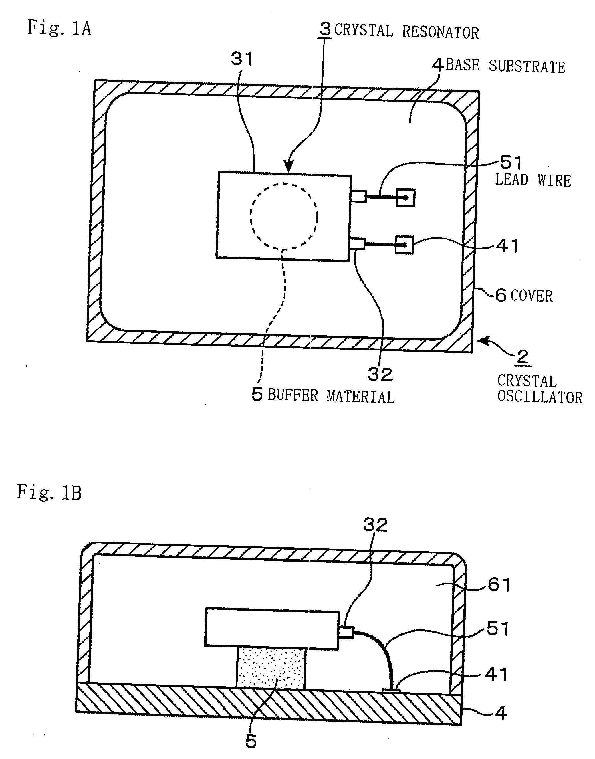
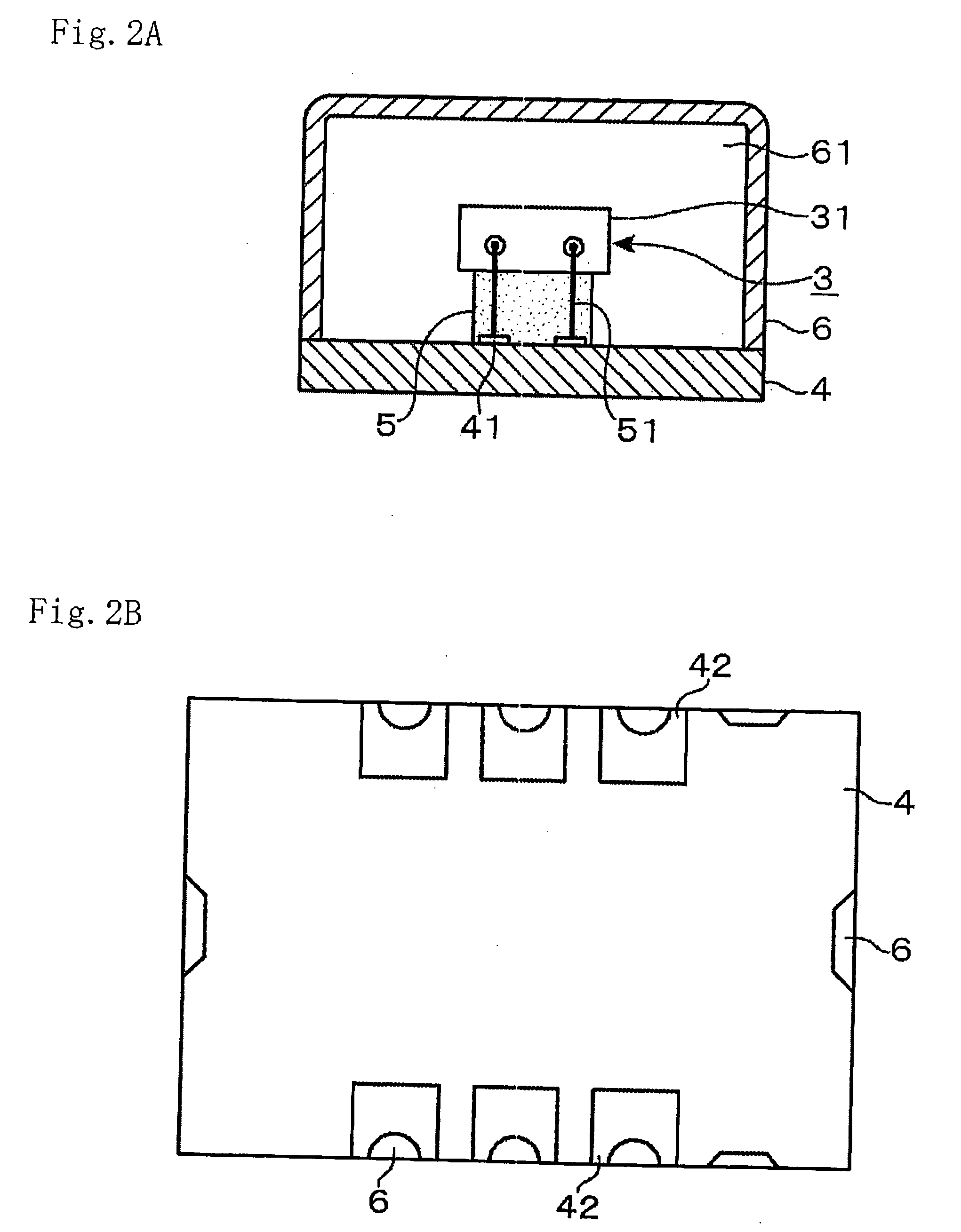
[0022] Hereinafter, as an example embodiment of a piezooscillator according to the present invention, a crystal oscillator 2 having a crystal resonator will be described with reference to the drawings. FIG. 1A shows a horizontal plane of the crystal oscillator 2 and FIG. 1B shows a vertical side face thereof, and FIG. 2A shows a vertical rear side face of the crystal oscillator 2 and FIG. 2B shows a reverse face thereof.

[0023] In the drawing, “3” denotes a crystal resonator being a piezoelectric resonator, and, in this example, a crystal piece and a pair of excitation electrodes to excite the crystal piece are structured to be enclosed in a square package 31. For example, on the rear side face portion of the square package 31, there are provided two electrodes 32 being electrically connected, for example, to the respective excitation electrodes.

[0024] In the drawing, “4” denotes a base substrate in which an oscillation circuit to oscillate the crystal resonator 3 is built, and a ...


PUM


Abstract

A piezooscillator having a piezoelectric resonator, composed of: a case surrounding a space where the piezoelectric resonator is provided and including a substrate and a cover; a buffer material supporting the piezoelectric resonator and suppressing a shock conveyed from the case to the piezoelectric resonator; and a wiring member electrically connecting the piezoelectric resonator and the substrate and having flexibility, or composed of: a case surrounding a space where the piezoelectric resonator is provided and including a first substrate and a cover; a second substrate mounting the piezoelectric resonator thereon; a buffer material supporting the second substrate and suppressing a shock conveyed from the case to the piezoelectric resonator; and a wiring member electrically connecting the first and second substrates and having flexibility, in which, when the case suffers the shock from outside, the buffer material absorbs the shock to prevent the shock conveyance to the piezoelectric resonator and frequency variation arising in the piezooscillator, realizing shock-resistance improvement, is provided.

Description

BACKGROUND OF THE INVENTION [0001] 1. Field of the Invention [0002] The present invention relates to a piezooscillator having a piezoelectric resonator. [0003] 2. Description of the Related Art [0004] As an example crystal oscillator having a crystal resonator being a piezoelectric resonator, that having a structure shown in FIGS. 7A, 7B, 7C, 7D is known. In FIGS. 7, “11” denotes a crystal resonator having a structure in which a crystal piece and a pair of excitation electrodes are enclosed in a square package while being held, for example, by a support member. In the drawing, “12” denotes a base substrate mounting the crystal resonator 11 thereon, and an oscillation circuit to oscillate the crystal resonator 11 is built in the base substrate 12. In the drawing, “13” denotes a lead wire, and, for example, one end of the lead wire 13 is connected to each excitation electrode in the package of the crystal resonator 11. Further, the other end of the lead wire 13 is connected to an elec...

Claims


Application Information

Patent Timeline
IPC IPC(8): H01L41/053
CPCH03H9/0514H03H9/1014H03H9/09H03H9/08
Inventor KASAHARA, KENJI
Owner NIHON DEMPA KOGYO CO LTD
Learn More