
System, method and apparatus for enhancing a projected image

a projection image and system technology, applied in the field of projection adapters, can solve the problems of high cost, inability to provide cinematic quality depth of field control, elusive depth of field (dof) problem, etc., and achieve the effect of reducing the optical depth of field, and enhancing a projected imag

Inactive Publication Date: 2007-02-15
REDROCK MICROSYST
View PDF19 Cites 23 Cited by
  • Summary
  • Abstract
  • Description
  • Claims
  • Application Information

AI Technical Summary

Benefits of technology

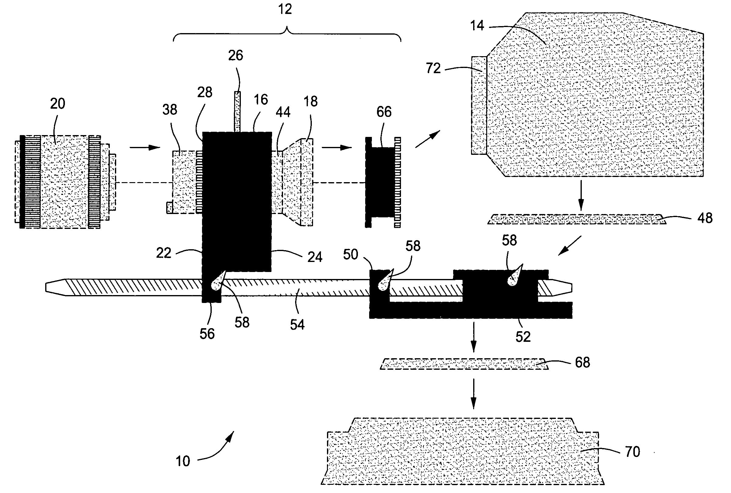
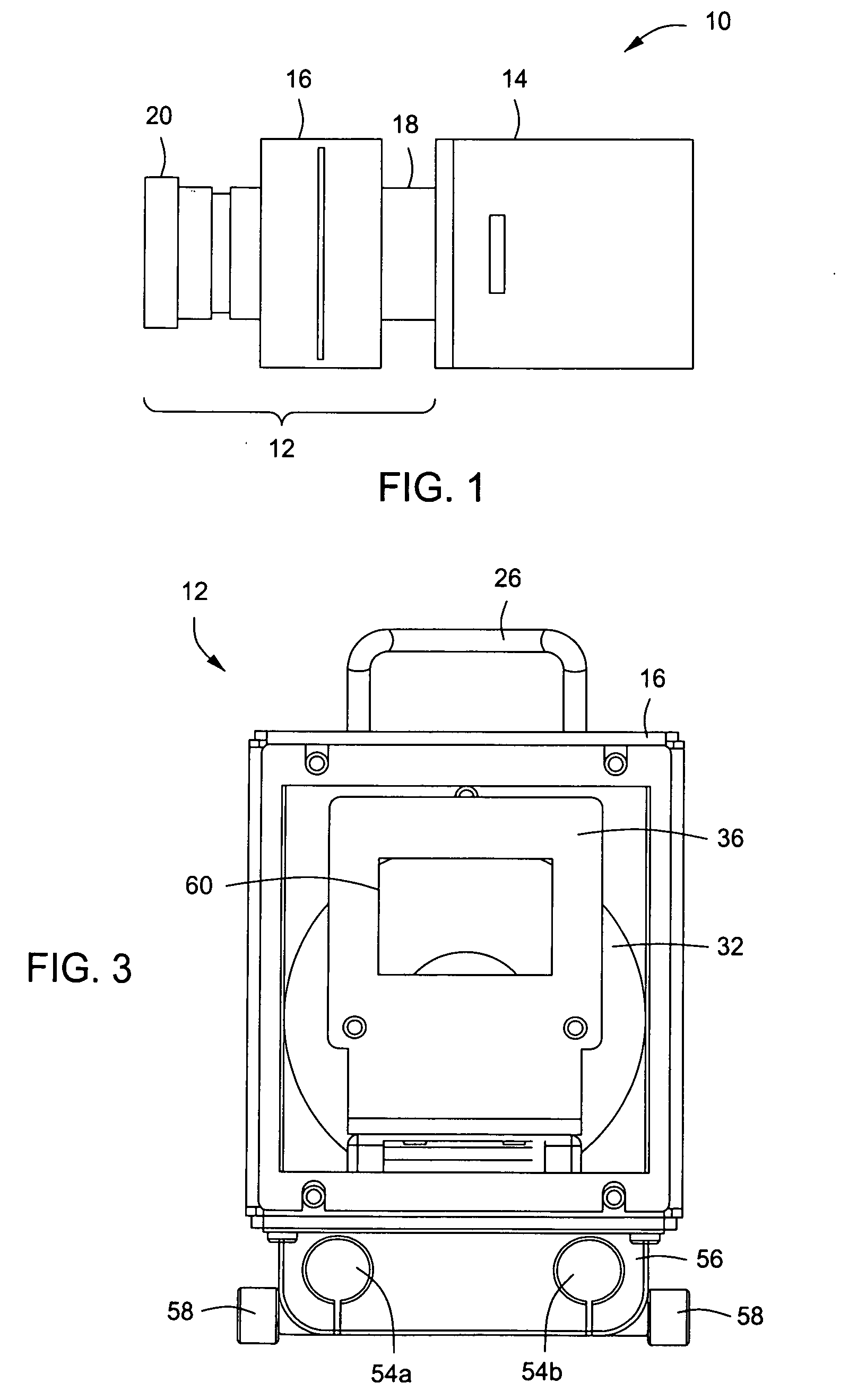
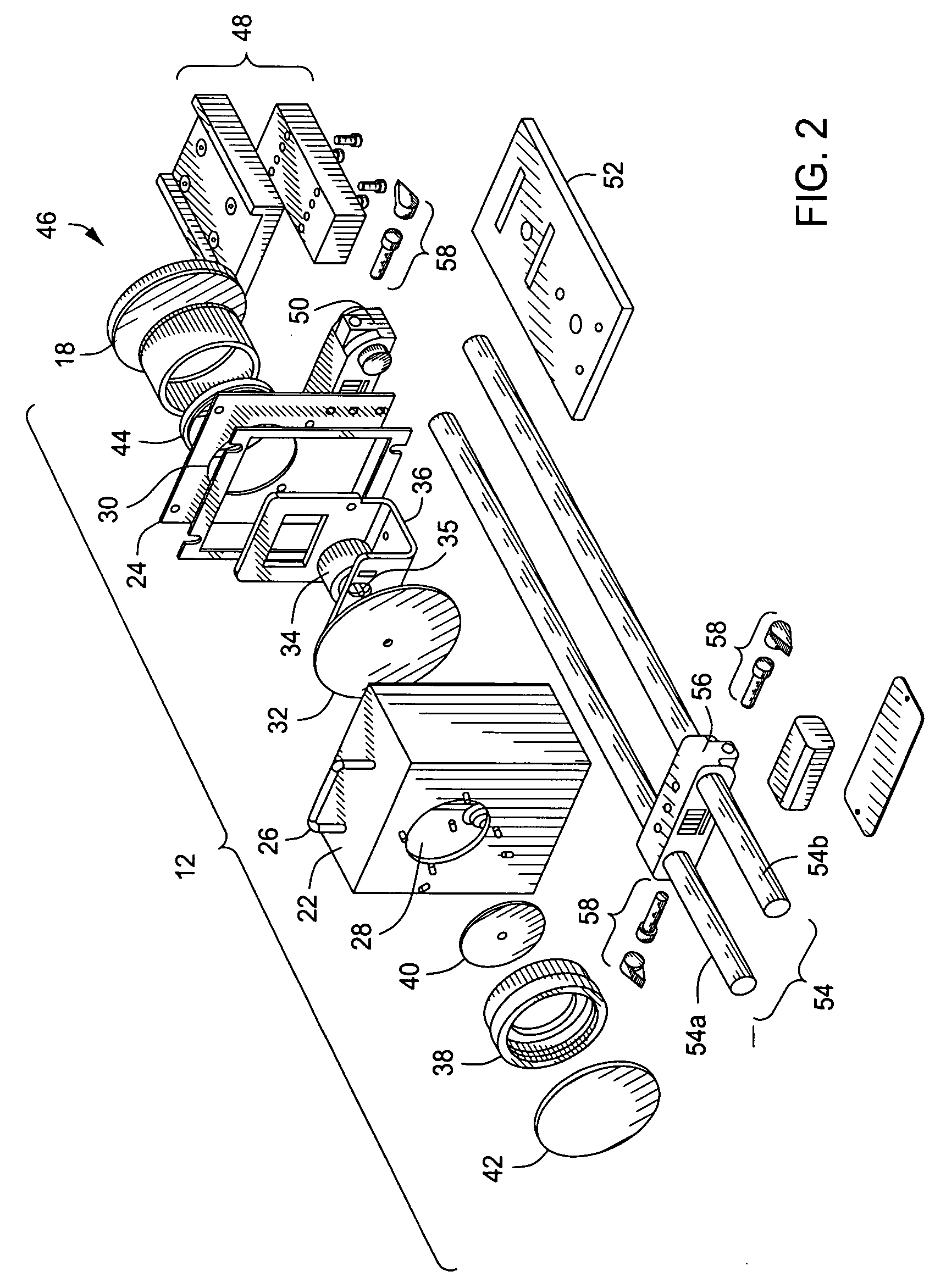
[0008] The present invention provides a system, method and apparatus for enhancing a projected image to reduce the optical depth of field, and create a more desirable film-like image. In addition, the present invention allows the use of interchangeable 35 mm lenses to allow filmmakers the freedom to achieve varying angles of view, focus, and a shallow depth of field that are commonly used in cinematic techniques where the objects the filmmaker wants to highlight is in focus, where everything else is blurred. More specifically, the present invention provides a multi-function imaging element for enhancing a projected image that includes a focusing screen that minimizes light hot spots in an image projected on the focusing screen and filters ultraviolet rays. The focusing screen can be a diffusion screen made of glass, ground glass, acrylic, crystalline wax or plastic that has been treated by sandblasting, laser etching or acid washing. Moreover, the focusing screen can be static, moving, oscillating or rotating. The ultraviolet rays are filtered using a coating on the focusing screen, or by a separate filter made of glass, plastic or film. Note that the multi-function imaging element can be integrated into an adapter, a camera, a video camera, a projector, a television, a monitor, or other image capture or display device.
[0009] Moreover, the present invention provides a method for providing an enhanced image by filtering light to reduce ultraviolet rays, diffusing the filtered light to minimize light hot spots, and projecting the diffused light on an image reception area to create the enhanced image.
[0012] Moreover, the present invention provides a system that includes an image capture or display device, a lens and a focusing screen disposed between the video camera and the lens that minimizes light hot spots in an image projected on the focusing screen and filters ultraviolet rays. The focusing screen can be disposed within an adapter and a mount can be connected to the image capture or display device, the lens and the adapter to stabilize the system.

Problems solved by technology

Although, video adapters for generic video cameras have been in use for years in an attempt to enhance the quality of the recorded image and reduce the optical depth of field to create a more desirable film-like image, they are typically complex, expensive and do not provide cinematic quality depth of field control.
The inability to use interchangeable 35 mm lenses has left the depth-of-field (DOF) problem elusive or too expensive to achieve.
The image sensors in most video cameras are too small to provide cinematic depth of field control.
It is very difficult to get an object in sharp focus in the foreground against a blurred background, to communicate depth with focus, and to provide cinematic rack focus for shifting attention in a scene with most video cameras.
More specifically, conventional video camera adapters are expensive and require many individual components to achieve the desired effect.
Moreover, each component adds cost and must be carefully selected and matched to meet the requirements of the overall system.
In addition, these conventional multi-function imaging elements negatively affect image quality.
For example, a separate DCX or Fresnel lens glued to the focusing screen; however, this approach degrades the image by reducing overall resolution and contrast of the projected image.
Also, another problem is long-term loss of optical quality as many adapters do not incorporate a UV filter and suffer from degrading image quality over time due to damage from UV light.
While these devices may be suitable for the particular purpose to which they address, they are less desirable for creating the look of 35 mm film with a more shallow focus using a video camera unit.

Method used


Image

  • System, method and apparatus for enhancing a projected image
  • System, method and apparatus for enhancing a projected image
  • System, method and apparatus for enhancing a projected image

Examples


Embodiment Construction

[0022] While the making and using of various embodiments of the present invention are discussed in detail below, it should be appreciated that the present invention provides many applicable inventive concepts that can be embodied in a wide variety of specific contexts. The specific embodiments discussed herein are merely illustrative of specific ways to make and use the invention and do not delimit the scope of the invention.

[0023] Although it is possible to create the right combination of lenses and adapters so that the light from a 35 mm lens could be focused directly onto the camera sensor, it does not create the desired effect: the 35 mm look. Depth of focus is related to image size. If the final image is ⅓rd of an inch (about 16 mm) then there will be a very deep focus. Getting an object in focus in the foreground against an out-of-focus background might require that the background be 50 feet or more behind the foreground. This deep focus is one characteristic of digital video...


PUM


Abstract

The present invention provides a system, method and apparatus for enhancing a projected image to reduce the optical depth of field, and create a more desirable film-like image. The present invention provides a multi-function imaging element for enhancing a projected image that includes a focusing screen that minimizes light hot spots in an image projected on the focusing screen and filters ultraviolet rays. The focusing screen can be static, moving, oscillating or rotating. The ultraviolet rays are filtered using a coating on the focusing screen, or by a separate filter made of glass, plastic or film. Note that the multi-function imaging element can be integrated into an adapter, a camera, a video camera, a projector, a television, a monitor, or other image capture or display device.

Description

TECHNICAL FIELD OF THE INVENTION [0001] The present invention relates in general to the field of image projection and adapters and more specifically to a system, method and apparatus for enhancing a projected image to reduce the optical depth of field, and create a more desirable film-like image. PRIORITY CLAIM [0002] This patent application is a non-provisional application of U.S. provisional patent application 60 / 699,704 filed on Jul. 14, 2005 and entitled “A Multi-Function Element to Improve Video Adapters,” which is hereby incorporated by reference in its entirety. BACKGROUND OF THE INVENTION [0003] Without limiting the scope of the invention, its background is described in connection with video camera units and video adapters. Although, video adapters for generic video cameras have been in use for years in an attempt to enhance the quality of the recorded image and reduce the optical depth of field to create a more desirable film-like image, they are typically complex, expensiv...

Claims


Application Information

Patent Timeline
Patent Type & Authority Applications(United States)
IPC IPC(8): G03B23/10G03B3/00
CPCG03B11/00G03B13/24H04N5/2254G03B21/14G03B17/56G03B17/565
Inventor HURD, JAMES
Owner REDROCK MICROSYST
Learn More