Bonding pattern discrimination program
a technology of discrimination and positioning patterns, applied in the field of bonding pattern discrimination, can solve the problems of poor positioning, poor precision, and inconvenient use of edge detection methods, and achieve the effect of reducing the inclination of positioning patterns used in bonding and reducing the inclination of the edge detection method
- Summary
- Abstract
- Description
- Claims
- Application Information
AI Technical Summary
Benefits of technology
Problems solved by technology
Method used
Image
Examples
embodiment 1
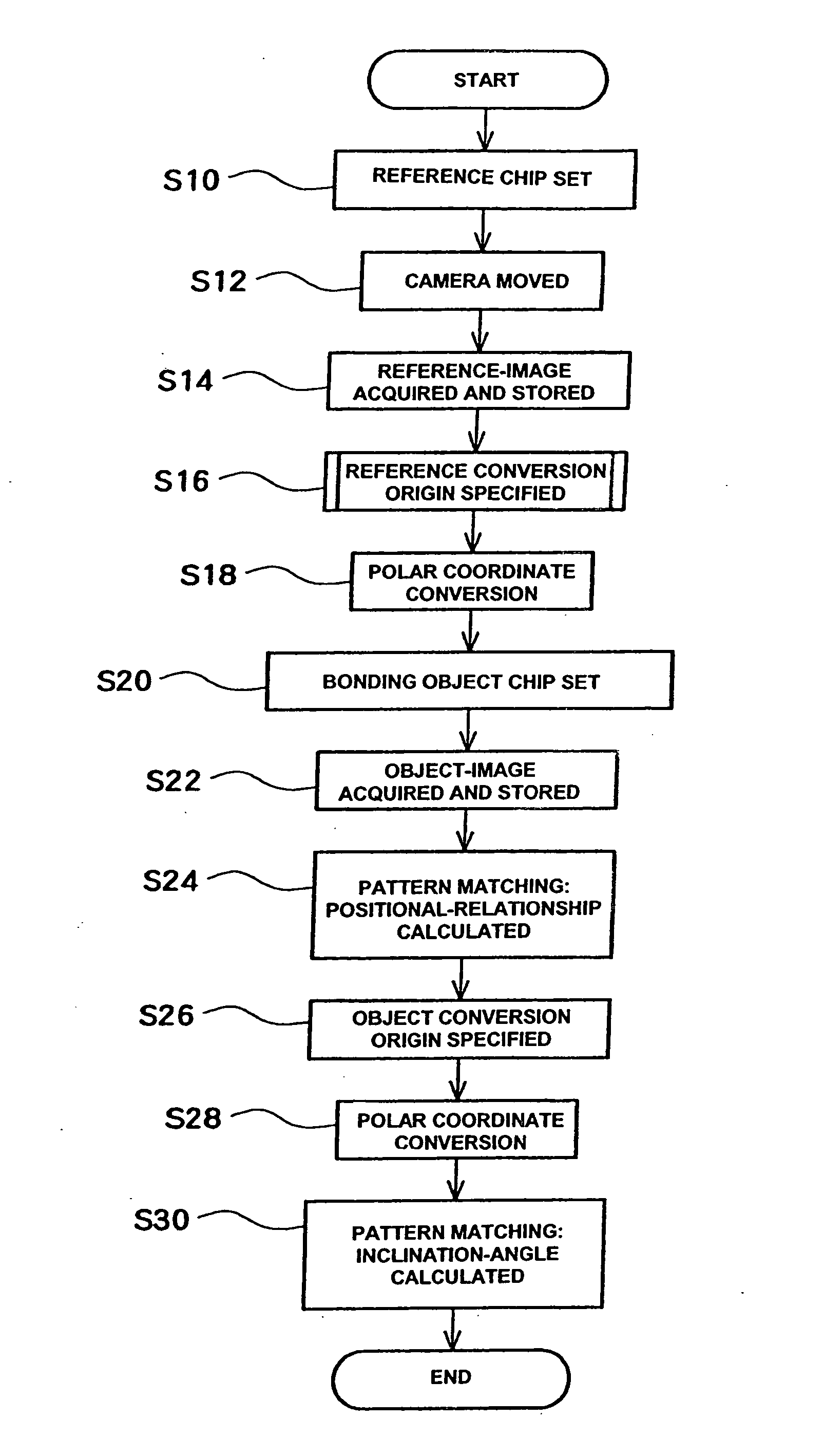
[0117]FIG. 8 is a block diagram of a wire bonding apparatus 100 by way of using the bonding pattern discrimination method of the present invention. Furthermore, a reference chip 90 or bonding object chip 92 used to discriminate the positioning pattern is also shown, although this is not a constituent element of the wire bonding apparatus 100.
[0118] The wire bonding apparatus 100 comprises an apparatus main body 102 and a control section 120. The apparatus main body includes a bonding head 104, a table 106 which moves the bonding head 104 within the XY plane shown in FIG. 8, and a stage 108 that holds the chips 90, 92. A tool 110 which bonds a wire to the chips, and a camera 112 which detects the positions of the chips 90, 92, are attached to the bonding head 104. The bonding head 104 is connected to the bonding head I / F 130 of the control section 120 by a single line. Similarly, the camera 112 is connected to the camera I / F 132, and the table 106 is connected to the table I / F 134, ...
embodiment 2
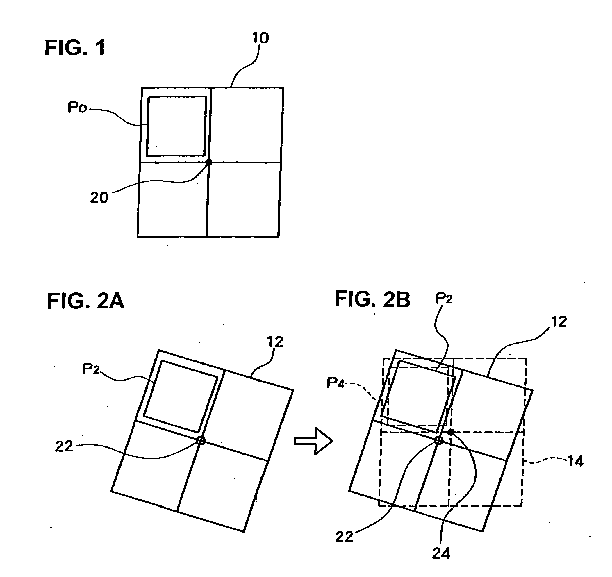
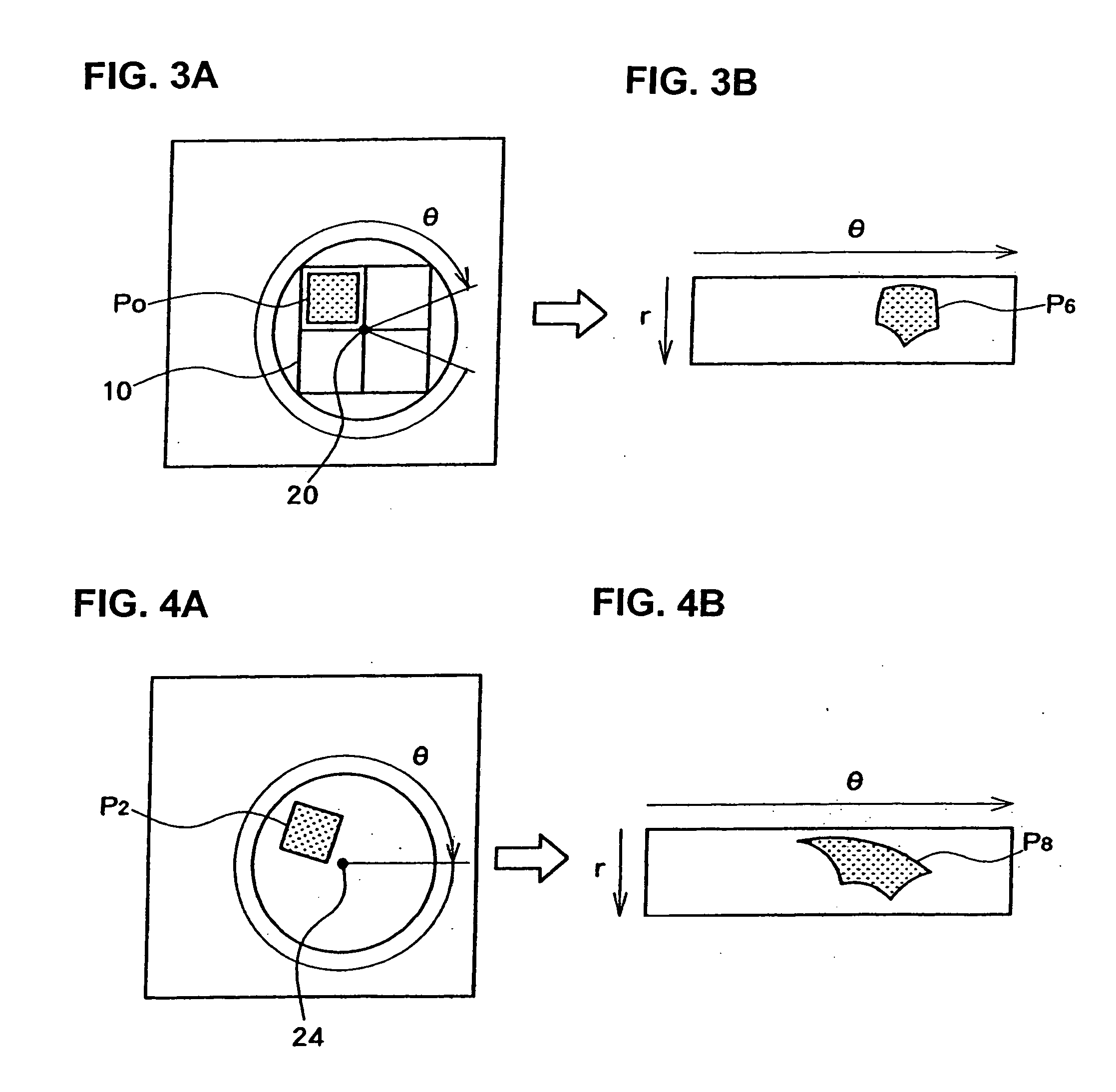
[0134] The more detailed content of the reference conversion origin specifying step will be described. Embodiment 2 corresponds to an embodiment in which the first embodiment in the above-described Japanese Patent Application Laid-Open (Kokai) No. 2002-208010 is applied to the boning positioning patterns. The detailed content of this reference conversion origin specifying step will be described with reference to the internal flow chart shown in FIG. 10, and FIGS. 11 through 16. In FIG. 10, and FIGS. 11 through 16, elements that are the same as elements shown in FIGS. 1 and 2 are labeled with the same symbols, and a detailed description of such elements is omitted. Furthermore, the procedure shown in the internal flow chart in FIG. 10 is performed by internal modules in the reference conversion origin specifying module 142 in the CPU 122 illustrated in FIG. 8.
[0135] The reference-image 10 acquired by the steps S10 through S14 illustrated in FIG. 9 is used to specify the reference co...
embodiment 3
[0145] Embodiment 3 corresponds to an embodiment in which the second embodiment in the above-described Japanese Patent Application Laid-Open (Kokai) No. 2002-208010 is applied to the bonding positioning pattern with regard to the reference conversion origin specification step. The detailed content of this reference conversion origin specification step will be described with reference to the internal flow chart shown in FIG. 17, and FIG. 18. The procedure of the internal flow chart shown in FIG. 17 is executed by internal modules of the reference conversion origin specifying module 142 in the CPU 122 illustrated in FIG. 8.
[0146] The reference-image 10 acquired in the steps S10 through S114 illustrated in FIG. 9 is also used for the specification of the reference conversion origin in Embodiment 3.
[0147] A plurality of rotational center points are set within this reference-image 10 (S60). The conditions of this setting are shown in FIG. 18. In this example, a plurality of rotational ...
PUM
| Property | Measurement | Unit |
|---|---|---|
| inclination-angle Δθ | aaaaa | aaaaa |
| angle | aaaaa | aaaaa |
| inclination-angle | aaaaa | aaaaa |
Abstract
Description
Claims
Application Information
 - R&D
- Intellectual Property
- Life Sciences
- Materials
- Tech Scout
- Unparalleled Data Quality
- Higher Quality Content
- 60% Fewer Hallucinations
Browse by: Latest US Patents, China's latest patents, Technical Efficacy Thesaurus, Application Domain, Technology Topic, Popular Technical Reports.
© 2025 PatSnap. All rights reserved.Legal|Privacy policy|Modern Slavery Act Transparency Statement|Sitemap|About US| Contact US: help@patsnap.com


