
Bonding pattern discrimination device

a discrimination device and positioning pattern technology, applied in the field of bonding pattern discrimination, can solve the problems of poor positioning, poor precision, and inconvenient use of edge detection methods, and achieve the effect of reducing the inclination of positioning patterns used in bonding and reducing the inclination of the edge detection method

Inactive Publication Date: 2007-02-15
SHINKAWA CO LTD
View PDF9 Cites 7 Cited by
  • Summary
  • Abstract
  • Description
  • Claims
  • Application Information

AI Technical Summary

Benefits of technology

This method allows for quick and precise discrimination of inclination angles, reducing processing time and improving accuracy in positioning chips and bonding pads, essential for high-precision bonding processes.

Problems solved by technology

In cases where chips are die-bonded to circuit boards, and in cases where wire bonding that connects wires to bonding leads of circuit boards from the bonding pads of chips disposed on the circuit boards is performed, there may be instances in which the positioning is poor so that the chips are disposed at an inclination.
The above-described prior art suffers from the following problems in the rapid, high-precision detection of the inclination of positioning patterns used in bonding.
Methods that determine the inclination by edge detection are not suitable for use in cases where considerable edges are not contained in the patterns, and the precision is influenced by the properties of the edges.
In methods that determine the inclination of line segments between separated positioning patterns, the visual field magnification drops if an attempt is made to observe both positioning patterns at the same time, so that the precision is poor; furthermore, time is required in order to observe respective positioning patterns in separate visual fields.
Furthermore, although a group of reference-images that are successively rotated from 0 to 360° can be prepared beforehand and pattern matching can be performed by way of using these reference-images, the quantity of data is enormous and the processing time is also lengthened.
However, there is no angle dependence of the developed pattern, so that actual angle detection is impossible.
In methods that calculate a rotation-resistant reference point, and take this point as a positioning point of bonding, positions can be determined with high precision, but the inclination-angle of the positioning patterns cannot be determined.
Thus, in the prior art, problems remain regarding the rapid, high-precision discrimination of the inclination of positioning patterns used in bonding.

Method used


Image

  • Bonding pattern discrimination device
  • Bonding pattern discrimination device
  • Bonding pattern discrimination device

Examples


embodiment 1

[0117] Embodiment 1

[0118]FIG. 8 is a block diagram of a wire bonding apparatus 100 by way of using the bonding pattern discrimination method of the present invention. Furthermore, a reference chip 90 or bonding object chip 92 used to discriminate the positioning pattern is also shown, although this is not a constituent element of the wire bonding apparatus 100.

[0119] The wire bonding apparatus 100 comprises an apparatus main body 102 and a control section 120. The apparatus main body includes a bonding head 104, a table 106 which moves the bonding head 104 within the XY plane shown in FIG. 8, and a stage 108 that holds the chips 90, 92. A tool 110 which bonds a wire to the chips, and a camera 112 which detects the positions of the chips 90, 92, are attached to the bonding head 104. The bonding head 104 is connected to the bonding head I / F 130 of the control section 120 by a single line. Similarly, the camera 112 is connected to the camera I / F 132, and the table 106 is connected to ...

embodiment 2

[0135] Embodiment 2

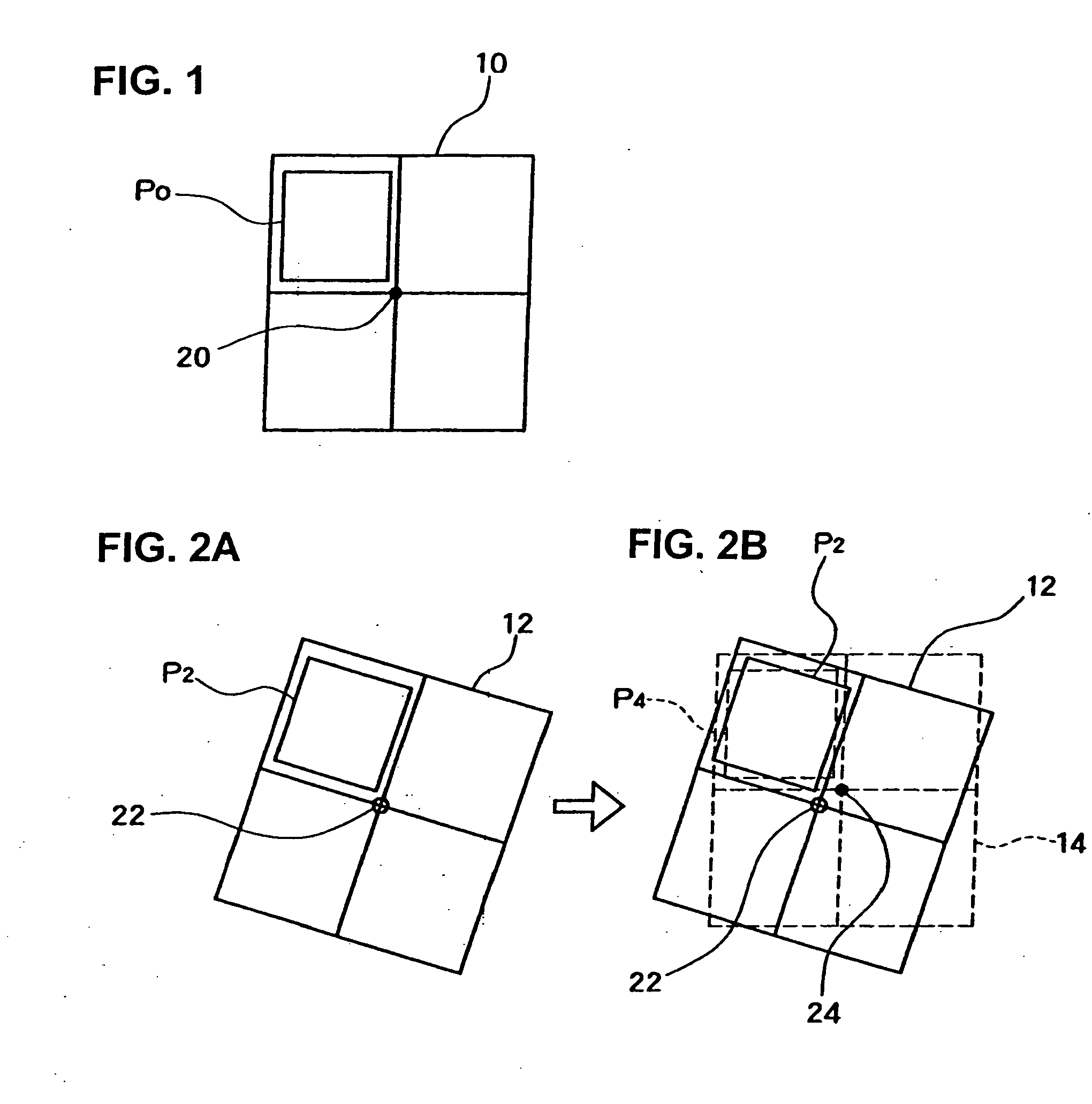
[0136] The more detailed content of the reference conversion origin specifying step will be described. Embodiment 2 corresponds to an embodiment in which the first embodiment in the above-described Japanese Patent Application Laid-Open (Kokai) No. 2002-208010 is applied to the boning positioning patterns. The detailed content of this reference conversion origin specifying step will be described with reference to the internal flow chart shown in FIG. 10, and FIGS. 11 through 16. In FIG. 10, and FIGS. 11 through 16, elements that are the same as elements shown in FIGS. 1 and 2 are labeled with the same symbols, and a detailed description of such elements is omitted. Furthermore, the procedure shown in the internal flow chart in FIG. 10 is performed by internal modules in the reference conversion origin specifying module 142 in the CPU 122 illustrated in FIG. 8.

[0137] The reference-image 10 acquired by the steps S10 through S14 illustrated in FIG. 9 is used to speci...

embodiment 3

[0147] Embodiment 3

[0148] Embodiment 3 corresponds to an embodiment in which the second embodiment in the above-described Japanese Patent Application Laid-Open (Kokai) No. 2002-208010 is applied to the bonding positioning pattern with regard to the reference conversion origin specification step. The detailed content of this reference conversion origin specification step will be described with reference to the internal flow chart shown in FIG. 17, and FIG. 18. The procedure of the internal flow chart shown in FIG. 17 is executed by internal modules of the reference conversion origin specifying module 142 in the CPU 122 illustrated in FIG. 8.

[0149] The reference-image 10 acquired in the steps S10 through S14 illustrated in FIG. 9 is also used for the specification of the reference conversion origin in Embodiment 3.

[0150] A plurality of rotational center points are set within this reference-image 10 (S60). The conditions of this setting are shown in FIG. 18. In this example, a plural...


PUM

PropertyMeasurementUnit
inclination-angle Δθaaaaaaaaaa
angleaaaaaaaaaa
inclination-angleaaaaaaaaaa

Abstract

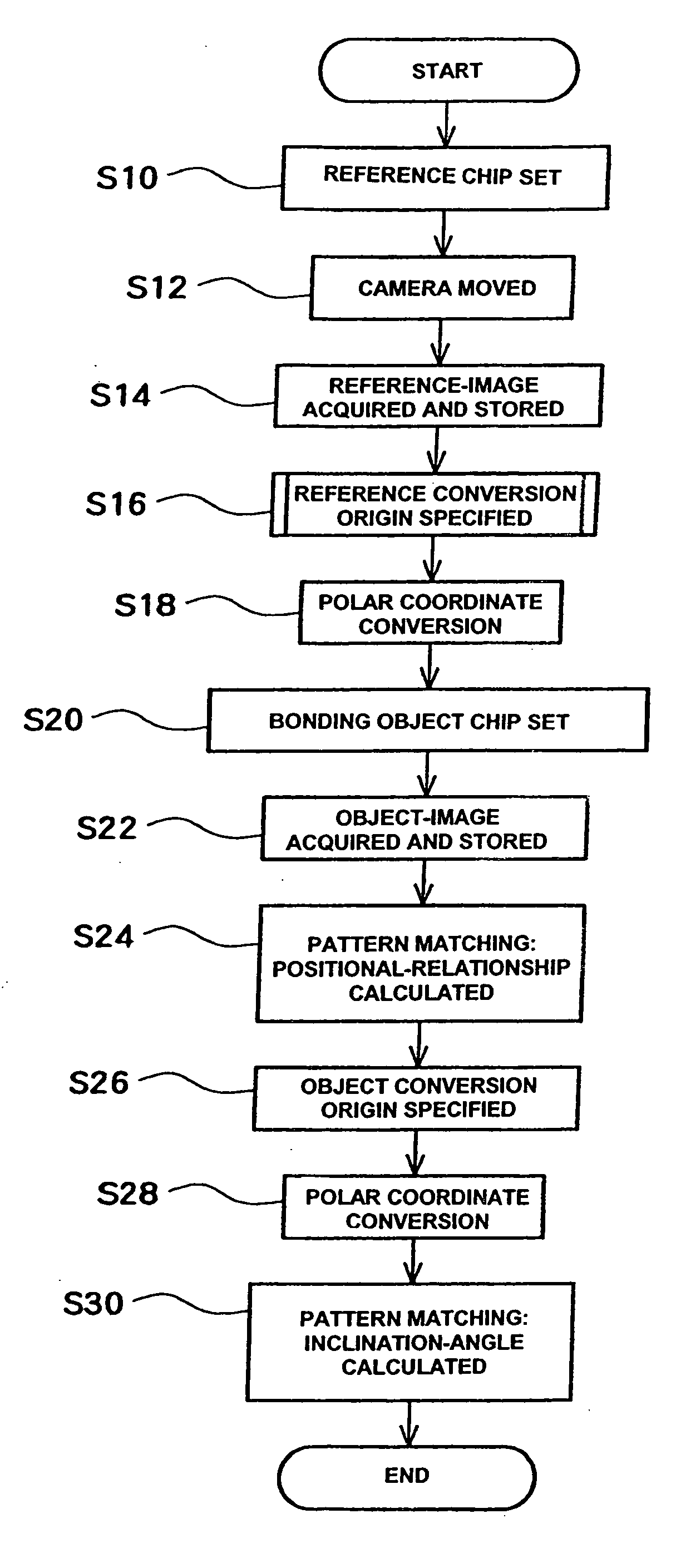
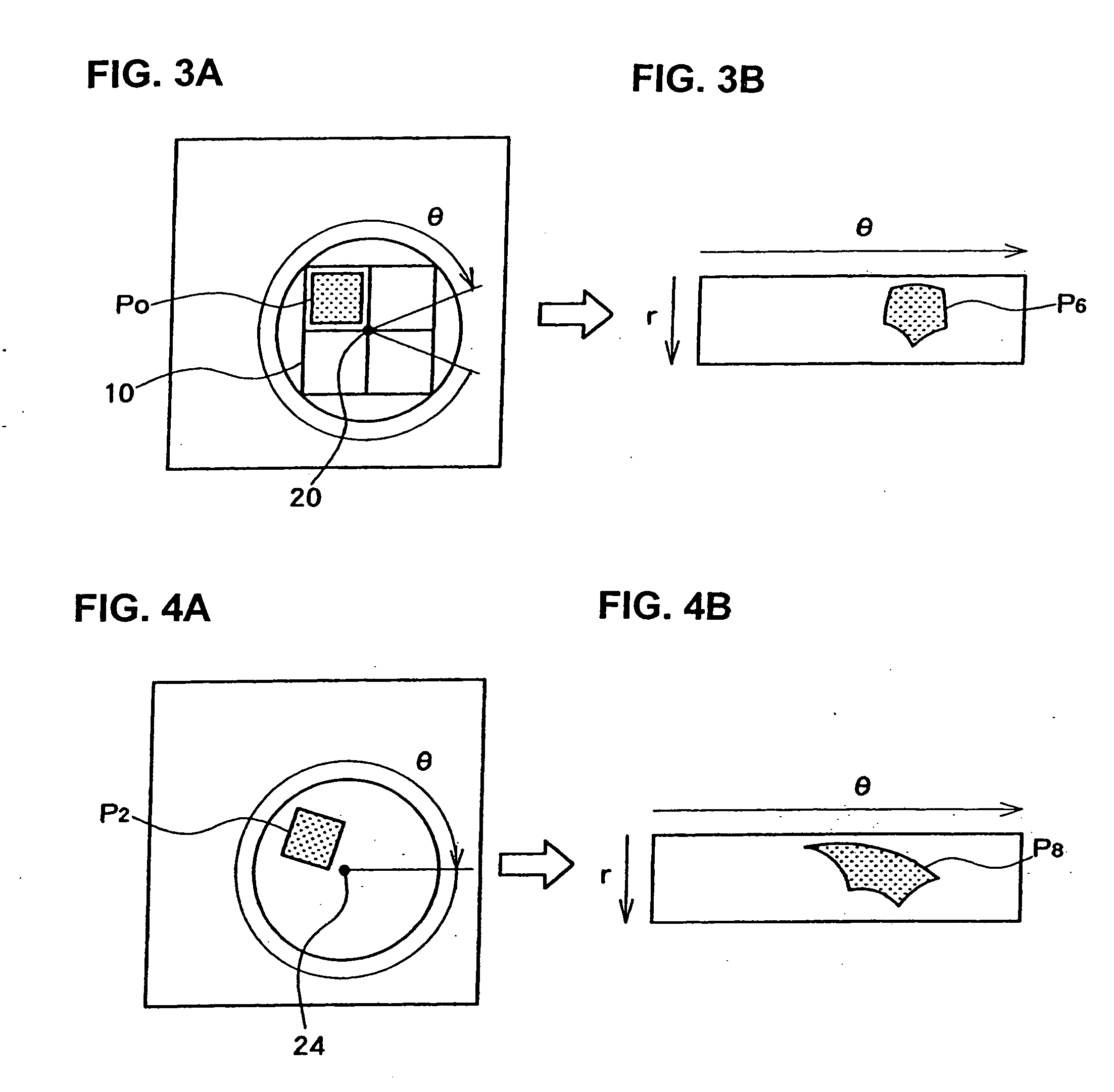
Determination of inclination of positioning patterns used in bonding being made by: imaging a positioning pattern of reference chip and taking such image as reference-image; specifying a polar coordinate conversion origin for the reference-image; imaging an object (chip) of bonding to use it as an object-image, thus obtaining a relative positional-relationship with the reference-image; specifying the polar coordinate conversion origin of the object-image, so that the object-image is subjected to a polar coordinate conversion; and calculating inclination-angle from both images that have been subjected to a polar coordinate conversion; thus using a point, in which an error in position of the object of comparison detected by pattern matching between an image, which is the object of comparison obtained by imaging the object of comparison disposed in an attitude that includes positional deviation, and the reference-image, shows a minimal value, as an origin of the polar coordinate conversion.

Description

BACKGROUND OF THE INVENTION [0001] 1. Technical Field [0002] The present invention relates to bonding pattern discrimination, and more particularly, to a bonding pattern discrimination method, a bonding pattern discrimination device and a bonding pattern discrimination program for discriminating the inclination of positioning patterns used in bonding. [0003] 2. Description of the Related Art [0004] In cases where chips are die-bonded to circuit boards, and in cases where wire bonding that connects wires to bonding leads of circuit boards from the bonding pads of chips disposed on the circuit boards is performed, there may be instances in which the positioning is poor so that the chips are disposed at an inclination. In order to prevent this, the external shapes of the chips themselves or positioning patterns formed on the surfaces of the chips are observed, and this inclination is detected. [0005] Methods in which the edges of the positioning patterns are detected and the inclinatio...

Claims


Application Information

Patent Timeline
Patent Type & Authority Applications(United States)
IPC IPC(8): G06K9/00H01L21/60B23K20/00G06V10/46H01L21/52
CPCB23K20/004B23K2201/32H01L2924/01084G06K9/3275G06K9/48G06T7/0044G06T2207/30141H01L24/78H01L24/85H01L2224/78301H01L2224/8513H01L2924/01002H01L2924/01006H01L2924/01027H01L2924/01082H01L2924/04953H01L2924/00014H01L2924/01005H01L2924/01033H01L2224/48G06T7/74B23K2101/32G06V10/243G06V10/46H01L2224/45099H01L2224/05599
Inventor ENOKIDO, SATOSHI
Owner SHINKAWA CO LTD
Learn More