Low-profile impeller bolt

a technology of impeller bolts and bolt heads, which is applied in the direction of pump components, non-positive displacement fluid engines, reaction engines, etc., can solve the problems of reducing pumping efficiency, affecting the speed of pumping, and affecting the efficiency of pumping, so as to achieve the effect of limiting the distan

Inactive Publication Date: 2007-02-15
ENVIROTECH PUMPSYSTEMS INC
View PDF14 Cites 7 Cited by
  • Summary
  • Abstract
  • Description
  • Claims
  • Application Information

AI Technical Summary

Benefits of technology

[0011] The present invention comprises a bolt for attaching the impeller to the terminal end of the drive shaft which is configured with a low-profile; that is, the bolt does not extend appreciably above the surface of the impeller and into the eye of the impeller. As a result, the impeller arrangement of the present invention allows the pump to process large-sized solids (e.g., three inches in diameter or larger) without having the solids become lodged between the impeller bolt and the wear plate.
[0012] The low-profile impeller bolt is generally formed with a unitarily formed shaft and head that eliminates the separate washer or spacer of prior art bolts. The head of the bolt of the present invention is substantially flattened in profile, thereby limiting the distance that the bolt extends into the eye of the impeller. As a result, larger solids that may be processed by the pump do not become lodged between the impeller and the wear plate of the pump.

Problems solved by technology

However, it has been shown that the size or diameter of solids that are reported to be processable by a pump are actually not able to be processed.
As a result, larger sized solids can become trapped or lodged between the head of the screw and the wear plate that is positioned adjacent the impeller on the suction side of the pump.
Solids lodged between the impeller and wear plate can cause the impeller to slow or stop in its rotation and / or can impede the flow of fluid through the pump, thereby leading to reduced pumping efficiency, or even pump failure.

Method used


Image

  • Low-profile impeller bolt
  • Low-profile impeller bolt

Examples


Embodiment Construction

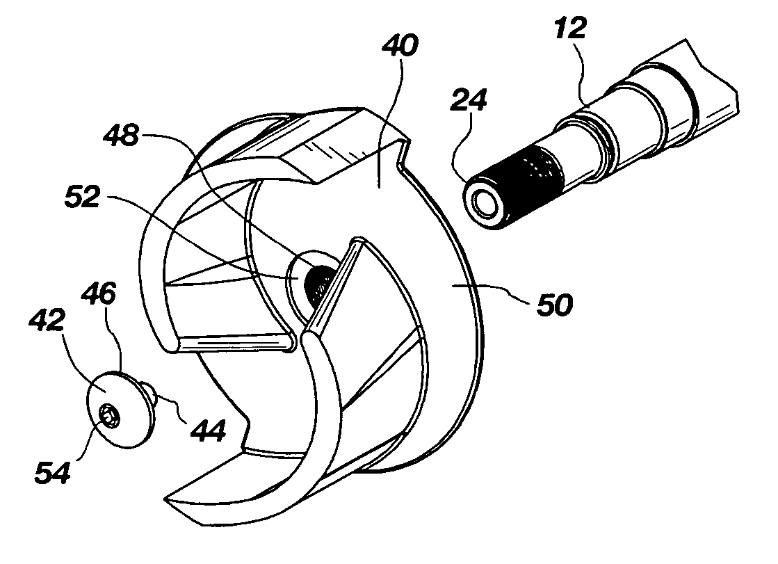
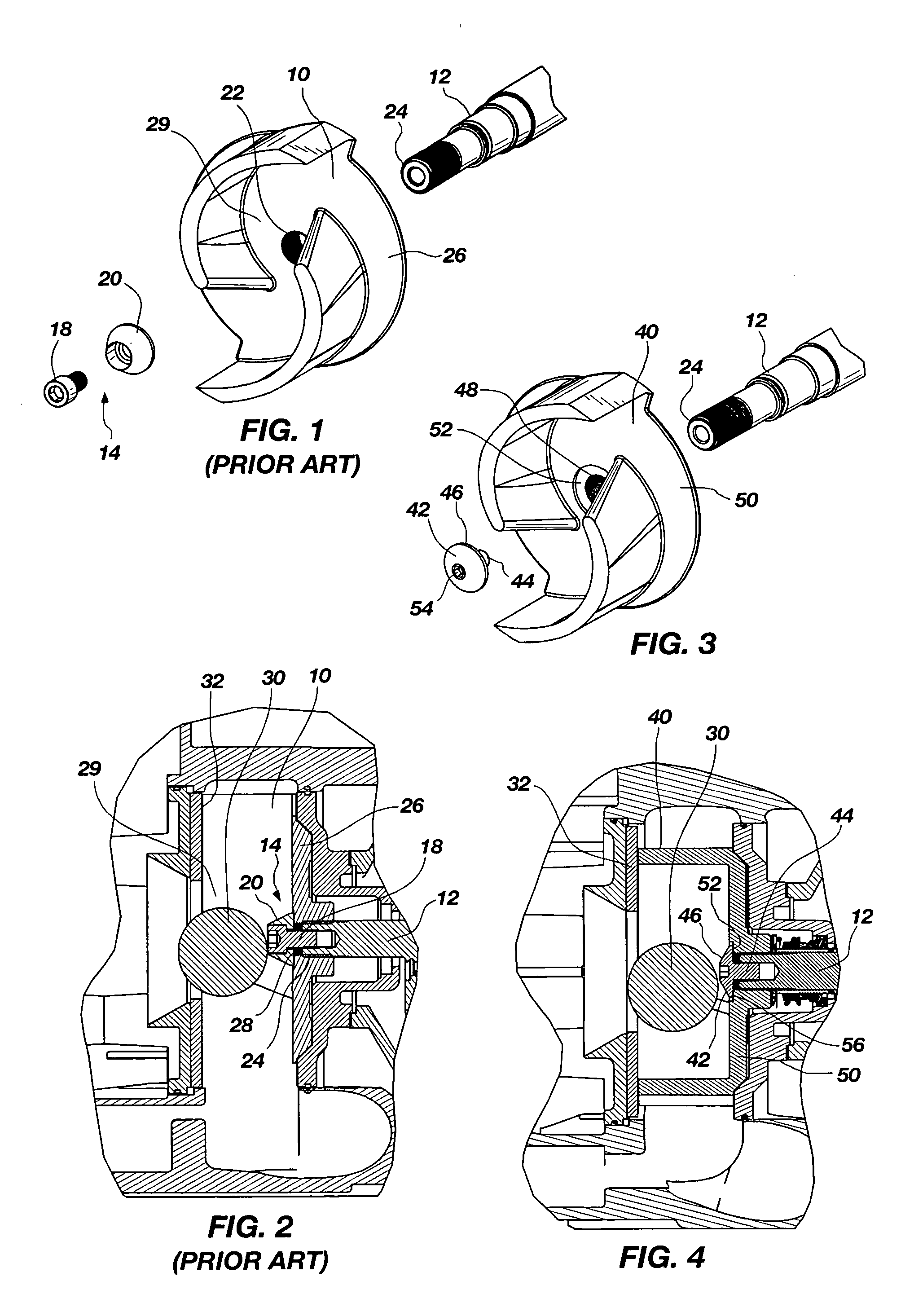
[0018] A typical impeller arrangement of the prior art is shown in FIGS. 1 and 2 as a comparative illustration of the problem solved by the present invention. In FIG. 1, which illustrates an exploded view of an impeller 10, drive shaft 12 and means 14 for attaching the impeller 10 to the drive shaft 12, the means 14 for attachment comprises a standard socket head cap screw 18 and a washer 20. As seen in FIGS. 1 and 2, the screw 18 fits through the washer 20 and through the central opening 22 in the impeller 10 to threadingly engage the terminal end 24 of the drive shaft 12.

[0019] The washer 20 typically used in prior art impeller attachment is conically-shaped. As best illustrated in FIG. 2, when the washer 20 is secured in place by the screw 18, the washer 20 is positioned against the surface of the base or shroud 26 of the impeller 10. The washer 20 consequently provides a spacer 28 between the screw 18 and the shroud 26 of the impeller 10. So configured, the screw 18 and washer ...


PUM


Abstract

An impeller for a self-primer pump is structured for attachment to the terminal end of a drive shaft by means of a bolt that is configured to provide a low profile such that the eye of the impeller is rendered capable of processing larger solids that are entrained in fluid.

Description

CROSS-REFERENCE TO RELATED APPLICATION [0001] This application is a non-provisional application claiming priority to provisional patent application Ser. No. 60 / 707,088 filed Aug. 10, 2005.BACKGROUND OF THE INVENTION [0002] 1. Field of the Invention [0003] This invention relates to self-priming centrifugal pumps which are used to process fluids containing solids. Specifically, this invention relates to providing an impeller bolt that has a low profile to thereby accommodate processing of fluids with larger solids entrained in the fluid. [0004] 2. Description of Related Art [0005] Self-priming centrifugal pumps are well-known and frequently used in industries where processing fluids with entrained solids is required. Self-primer pumps, also known as trash pumps, are characterized as having a casing which houses a suction chamber and a separation chamber divided by a wall or plenum. An impeller positioned in a volute section of the pump receives fluid from the suction chamber and deliv...

Claims


Application Information

Patent Timeline
Patent Type & Authority Applications(United States)
IPC IPC(8): F04D29/00
CPCF04D29/20
Inventor PAULIN, GREG
Owner ENVIROTECH PUMPSYSTEMS INC
Why Eureka
Try Eureka