
Integrated circuit device and low noise block down converter including same

Inactive Publication Date: 2007-02-15
SHARP KK
View PDF11 Cites 7 Cited by
  • Summary
  • Abstract
  • Description
  • Claims
  • Application Information

AI Technical Summary

Benefits of technology

[0048] The present invention was done to solve the above-described problem, and the objective of the present invention is to provide an integrated circuit device suitable for a signal recombination circuit that can reduce the leakage of the input signals, and a low noise block down converter including the integrated circuit device.
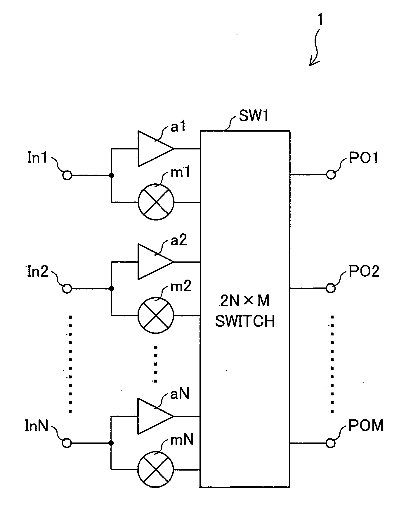
[0050] According to the arrangement above, the integrated circuit device of the present invention is arranged in such a manner that the input signals are supplied through (i) a path where the frequency conversion of the input signal is carried out and (ii) a path where the frequency conversion is not carried out. In this manner, the signals which are subjected to frequency conversion and the signals which are not subjected to frequency conversion are generated from N input signals, and the 2N×M switch section selects, from those 2N signals, a required signal and sends the selected signal to a desired output selected from M outputs. As a result, being different from the conventional art, it is unnecessary to switch the path by using switches in accordance with whether or not frequency conversion is carried out. It is therefore possible to reduce the leakage of the input signals on account of the switching of the path. Consequently, an integrated circuit device suitable for a signal recombination circuit that can reduce the leakage of the input signals is provided.
[0052] According to this arrangement, the low noise block down converter of the present invention can reduce the leakage of the input signals, by adopting the aforesaid integrated circuit device in the signal recombination circuit.

Problems solved by technology

As a result, being different from the conventional art, it is unnecessary to switch the path by using switches in accordance with whether or not frequency conversion is carried out.

Method used


Image

  • Integrated circuit device and low noise block down converter including same
  • Integrated circuit device and low noise block down converter including same
  • Integrated circuit device and low noise block down converter including same

Examples


embodiment 1

[0067] The following will describe an embodiment of the present invention in reference to figures. Described below is a case where an integrated circuit device (hereinafter, switch block) of the present invention is a part of a signal recombination circuit of a LNB.

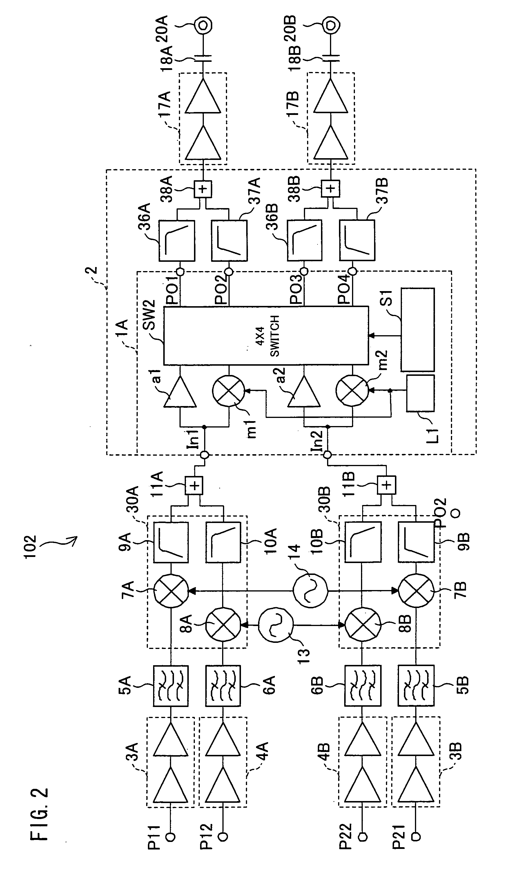
[0068]FIG. 2 is a circuit diagram of a LNB 102, in which the signal recombination circuit 55 in FIG. 13 is replaced by a signal recombination circuit 2 of the present embodiment. Since the circuit configuration of the LNB 102 has already been described in Background of the Invention, the description thereof is omitted. Also, members having the same functions are given the same numbers, unless otherwise stated.

[0069] The signal recombination circuit 2 receives a first synthesized signal and a second synthesized signal. Since the first and second synthesized signals are generated in the same manner as the aforesaid first and second synthesized signal in the conventional art, the description thereof is omitted.

[0070] As s...

embodiment 2

[0139]FIG. 10 outlines a switch block 1B in a signal recombination circuit 2 of another embodiment of the present invention. It is noted that members having the same numbers as those in the switch block 1A have the same functions, unless otherwise stated.

[0140] As shown in the figure, the switch block 1B includes low noise amplifiers (LNAs) lna1 and lna2, amplifiers a1 and a2, mixers m1 and m2, a 4×2 switch circuit SW5, a local signal generator L1, and a control device S1. Input terminals In1 and In2 are input terminals of the switch block 1B, whereas output terminals PO1 and PO2 are output terminals of the switch block 1B.

[0141] The low noise amplifier lna1 subjects, to low noise amplification, the first synchronized signal supplied to the input terminal In1. The low noise amplifier lna2 subjects, to low noise amplification, the second synchronized signal supplied to the input terminal In2. The 4×2 switch circuit SW5 is an example of the 2N×M switch circuit SW1.

[0142] The follow...


PUM


Abstract

A switch block 1 includes: N inputs; M outputs; N amplification sections each of which amplifies one of each pair of 2N input signals which are generated by dividing N input signals supplied to the N inputs in two; N bandwidth conversion sections each of which subjects, to frequency conversion, the other one of each pair of 2N input signals; and a 2N×M switch section which outputs the 2N output signals, which are supplied from the N amplification sections and the N bandwidth conversion sections, to either: one of the M outputs; or none of the M outputs. With this arrangement, it is possible to provide a signal recombination circuit which can reduce the leakage of the input signals.

Description

[0001] This Nonprovisional application claims priority under 35 U.S.C. § 119(a) on Patent Application No. 232494 / 2005 filed in Japan on Aug. 10, 2005, the entire contents of which are hereby incorporated by reference. FIELD OF THE INVENTION [0002] The present invention relates to an integrated circuit device provided in a low noise block down converter (hereinafter, LNB). BACKGROUND OF THE INVENTION [0003] LNBs for satellite broadcast receivers have been developed. An LNB receives a polarized signal supplied from a satellite, and converts the polarized signal into a signal in an IF frequency band (950 MHz-2150 MHz). [0004]FIG. 11 outlines a satellite broadcast receiver 101. The satellite broadcast receiver 101 includes an LNB 102, a tuner 103, and a tuner 104. The satellite broadcast receiver 101 is connected to an antenna 100 and a TV receiver 105. [0005] How the components of the satellite broadcast receiver 101 operate is briefly described. The LNB 102 receives, from the antenna ...

Claims


Application Information

Patent Timeline
IPC IPC(8): H04B7/14H04B1/18H04B1/26
CPCH01Q1/247H04N7/20H04H40/90
Inventor SAKURAI, SHOJINAKANO, YOSHIAKI
Owner SHARP KK
Learn More