Running controller and electric running control system for electric vehicle

Inactive Publication Date: 2007-02-15
HITACHI LTD
View PDF17 Cites 60 Cited by
  • Summary
  • Abstract
  • Description
  • Claims
  • Application Information

AI Technical Summary

Benefits of technology

[0020] With those features, when a tire slip occurs during running of the vehicl

Problems solved by technology

With the motor braking/driving control as disclosed in JP-UA-5-2501, however, the following problem occurs because the motor output and the regenerative braking force are controlled depending on the difference in rotation speed between the drive wheel and the driven wheel.
With the motor braking/driving control as

Method used


Image

  • Running controller and electric running control system for electric vehicle
  • Running controller and electric running control system for electric vehicle
  • Running controller and electric running control system for electric vehicle

Examples


Example

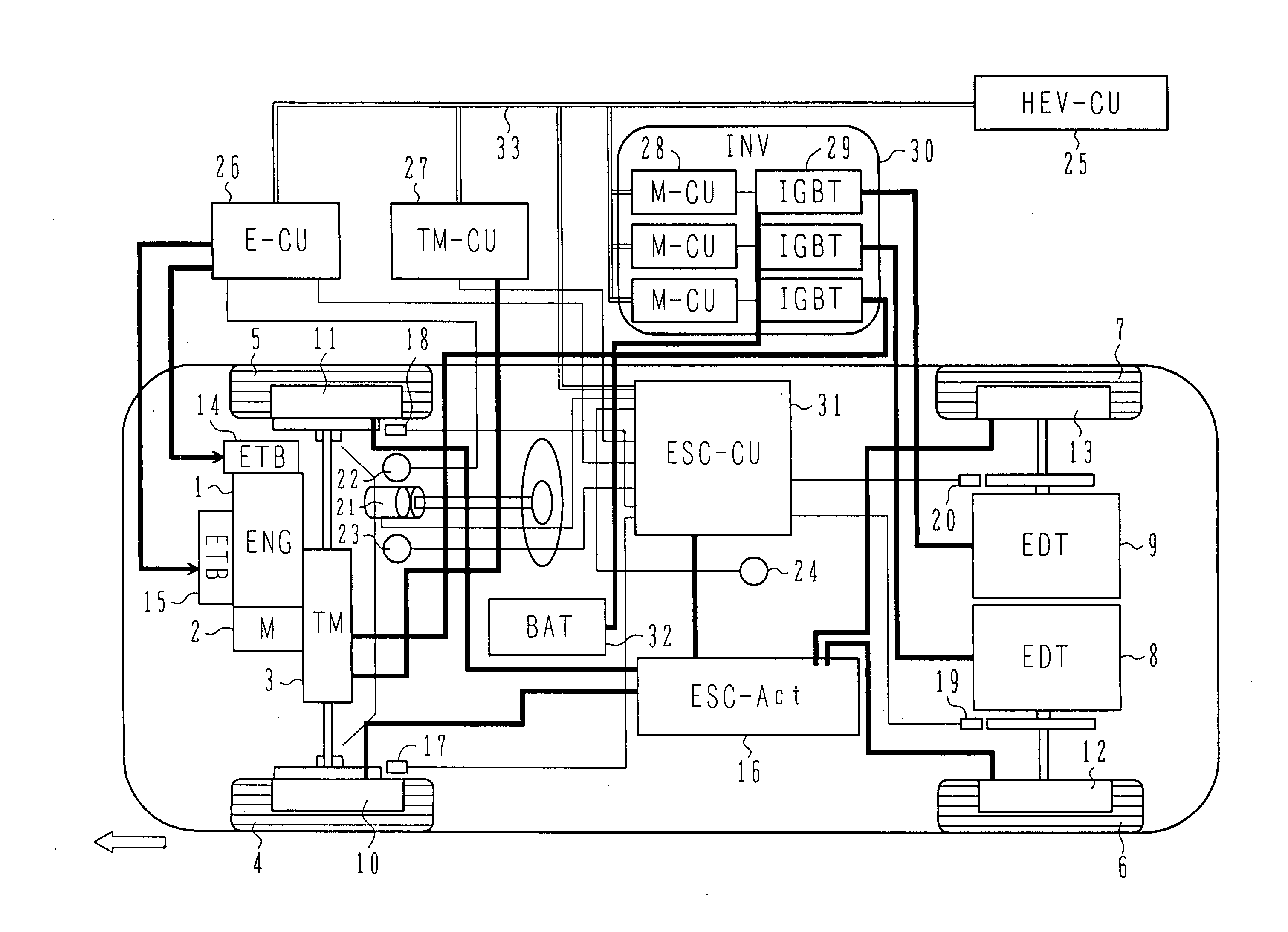
[0050] The construction and operation of a running controller and an electric running control system for an electric vehicle according to one embodiment of the present invention will be described below with reference to FIGS. 1-28. The following description is made in connection with, e.g., a hybrid electric vehicle employing a motor and an internal combustion engine as driving sources, which is one example of electric vehicles.

[0051] The internal combustion engine is a motive power source for outputting motive power with burning of fuel and is, for example, a gasoline engine, a diesel engine, or a gas engine gaseous fuel, such as hydrogen gas. In the following description, the internal combustion engine is referred to simply as the engine.

[0052] First, the construction of the electric vehicle equipped with the running controller and the electric running control system for the electric vehicle according to one embodiment will be described below with reference to FIG. 1.

[0053]FIG....


PUM


Abstract

A running controller and an electric running control system for an electric vehicle, in which when a tire slip occurs during running of the vehicle, such as under driving, braking and turning, a motor output is controlled to always maximize the coefficient μ of road friction, thereby obtaining a maximum tire driving force and a maximum tire braking force. In the electric vehicle, wheels are driven and braked through control of electric driving apparatuss each including a motor. When slipping of any of the wheels is detected, ESC-CU executes powering and regenerative control of the motor to change, depending on road conditions, a target value to which a slip rate is to be converged. The ESC-CU calculates the coefficient μ of road friction based on a motor current and executes the powering and regenerative control of the motor such that the calculated coefficient μ of road friction is maintained in the vicinity of a maximum value thereof.

Description

BACKGROUND OF THE INVENTION [0001] 1. Field of the Invention [0002] The present invention relates to a running controller and an electric running control system for an electric vehicle, such as an electric car or a hybrid car, in which at least one of wheels of the vehicle is driven by a motor for running of the vehicle. [0003] 2. Description of the Related Art [0004] In one example of known electric vehicles, such as electric cars or hybrid cars, each of which employs a motor as a driving source, a motor output and a regenerative braking force are controlled depending on the difference in rotation speed between a drive wheel and a driven wheel, thereby eliminating a wheel slip in a motor driving mode and a regenerative braking mode, as disclosed in JP-UA-5-2501. SUMMARY OF THE INVENTION [0005] With the motor braking / driving control as disclosed in JP-UA-5-2501, however, the following problem occurs because the motor output and the regenerative braking force are controlled depending...

Claims


Application Information

Patent Timeline
IPC IPC(8): G06F17/00B60K6/44B60K6/52B60L15/20B60L50/16B60W10/06B60W10/08B60W20/00F02D29/02
CPCB60L3/10Y02T10/7258Y02T10/7005B60L11/18B60L50/60Y02T10/70Y02T10/72
Inventor SEKIGUCHI, HIDEKIHAMAI, KYUGO
Owner HITACHI LTD
Why Eureka
Try Eureka