System and method for supplying breathing gas to a diver

a technology for providing breathing gas and diver, which is applied in the field of systems for providing breathing gas to diver, can solve the problems of affecting the flow of gas through the hose, etc., and achieves the effects of reducing wind or water resistance, reducing the amount of gas flowing through the hose, and reducing the difficulty of users moving freely

Inactive Publication Date: 2007-02-22
INTERSPIRO AB
View PDF14 Cites 14 Cited by
  • Summary
  • Abstract
  • Description
  • Claims
  • Application Information

AI Technical Summary

Benefits of technology

[0014] By virtue of the fact that the breathing gas is conveyed through the hose under the high pressure which is delivered from the gas source, a sufficiently great gas flow through the hose can be ensured even if the hose is designed with a relatively small inner cross-sectional area. With a suitable choice of hose material, the outer circumference of the hose can then also be kept small, the hose then constituting during use considerably smaller wind or water resistance than was previously possible. The small cross-sectional dimension of the hose also reduces the weight of the hose, which makes both the work at the site of the diver and transport, installation and setting in operation of the system easier. A hose with a small cross-sectional dimension is moreover more flexible and easier to handle, which also makes both the work of the diver at the site and letting-out and hauling-in of the hose easie...

Problems solved by technology

In particular in the case of long hoses, this causes considerable problems as the hose has to be designed with a relatively large inner cross-sectional area.
This results in the hose having to be made relatively thick, which in turn leads to the hose being heavy and unwieldy to handle.
Moreover, such a thick hose constitutes considerable wind resistance when it is used outdoors on land, which of course makes it more difficult for the user to move unhindered.
This problem is even worse for a diver because a thick hose constitutes great water resistance and because the action of the water on the hose results in great forces which are difficult to deal with but have to be overcome and resisted by the diver.
It is especially disadvantageous and even dangerous to u...

Method used


Image

  • System and method for supplying breathing gas to a diver
  • System and method for supplying breathing gas to a diver

Examples


first embodiment

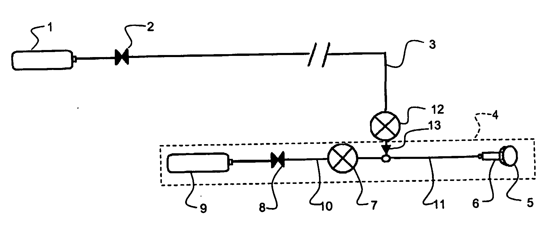
[0020]FIG. 1 shows a diagrammatic sketch of the invention, and

second embodiment

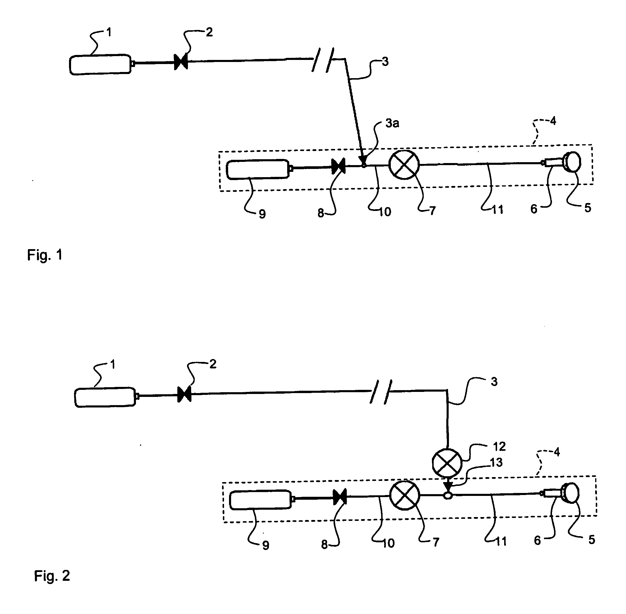
[0021]FIG. 2 shows a corresponding diagrammatic sketch of a

[0022]FIG. 1 shows a first embodiment of a system according to the invention. The system comprises a gas source in the form of a pressurized container 1 which contains breathing gas, for example air or nitrox. The container is of the standard type found on the market. These standard containers have different maximum pressure for different markets. The maximum pressure, which corresponds to the pressure in the container when it is full, is 200 bar on some markets, for example, while it is 300 bar on other markets. Containers with a maximum pressure of 700 bar are also found. All these different standard containers, but also other containers which deliver breathing gas under high pressure, can be used in the system according to the invention. The main point is that the container can deliver exhalation gas under a pressure which is considerably higher than the ambient pressure surrounding the diver.

[0023] The container is conn...


PUM


Abstract

The invention concerns a system and a method for supplying breathing gas to a diver. The system is of the open circuit type and comprises a gas source consisting of a pressurized container (1), which is intended to be placed at a distance from the diver and which delivers breathing gas under a high pressure, a breathing apparatus (4) which is intended to be carried by the diver and a flexible tube (3), which connects the gas source with the breathing apparatus. The flexible tube is of the high-pressure type, the gas is conducted through the flexible tube under a pressure, which is essentially equal to the pressure delivered from the gas source, and the gas source is arranged to be able to deliver breathing gas at a pressure, which exceeds approx. 30 bars.

Description

FIELD OF THE INVENTION [0001] The invention relates to a system for providing a diver with breathing gas, the system being an open system and comprising an external gas source in the form of a pressurized container which is intended to be located at a distance from the diver and which delivers breathing gas under high pressure, a breathing device which is intended to be worn by the diver, and a hose which connects the external gas source to the breathing device. The invention also relates to a method for providing a diver with breathing gas. [0002] The system can be used in, for example, what is known as surface-supplied diving or deep diving, the diver, via a hose, being provided with breathing gas from pressurized gas containers located above the surface of the water or in a space which may be located below the surface of the water. The system can also be used in smoke-helmeted firefighting or other hose diving where the user or diver is provided with breathing gas via a hose from...

Claims


Application Information

Patent Timeline
IPC IPC(8): B63C11/02A62B7/02B63C11/18B63C11/20
CPCA62B7/02B63C11/202B63C11/18
Inventor BUHLMANN, PIERREBOTOS, IMRE
Owner INTERSPIRO AB
Why Eureka
Try Eureka