Circuit card synchronization within a standardized test instrumentation chassis

a test instrument and circuit card technology, applied in the direction of instruments, digital transmission, generating/distributing signals, etc., can solve the problems of high cost of conventional state-of-the-art ate test systems, specialized and complex nature of ate test systems, and high cost of specialized hardware and software. , the development of specialized hardware and software is expensive and time-consuming and difficult to utiliz

Inactive Publication Date: 2007-02-22
ADVANTEST CORP
View PDF5 Cites 13 Cited by
  • Summary
  • Abstract
  • Description
  • Claims
  • Application Information

AI Technical Summary

Benefits of technology

[0026] When one module detects a mismatched condition (an unexpected DUT output), it may drive the PXI_LOCAL bus line that is being used as a MATCH line low as an indication of mismatched conditions. This mismatched condition will be detected by the other modules, which will either continue or repeat a portion of their local test programs, as appropriate.
[0027] An EOT line is similarly provided over PXI_LOCAL to enable any one pincard module to abruptly end the local test programs running in all other pincard modules if an error is detected by the local test program in the pincard module. By enabling modules to drive an EOT line that can be read by all other modules, the local test programs in all modules can be stopped without intervention by the global test system program in the controller. The EOT line may be provided over one of the same PXI_LOCAL bus lines used to carry known sequences for starting modules. Any module that experiences an error condition may drive the EOT line low, and all modules may subsequently read the EOT line to determine if any module has experienced an error condition. If any module experienced an error condition and drove the EOT line low, then all modules will immediately end their local test programs.
[0028] The precise timing and synchronization described above may be expanded to multi-chassis test systems. In multi-chassis embodiments, PXI_CLK10, LCM, START, MATCH and EOT from a PXI-compliant master star trigger card in chassis may be sent to a PXI-compliant slave star trigger card in one or more other PXI-compliant chassis via matched length differential cables and separate connectors on the master star trigger card. A dedicated connector may be employed for each chassis to ensure that the delay to each chassis is the same.

Problems solved by technology

A major reason for the high cost of conventional state-of-the-art ATE test systems is the specialized and complex nature of the ATE tester architecture.
ATE tester manufacturers typically employ a number of ATE tester platforms that are not only incompatible across companies, but also incompatible across platforms.
Because of these incompatibilities, each ATE tester may require its own specialized hardware modules and software components that cannot be used on other ATE testers.
This specialized hardware and software is expensive to develop and time-consuming and difficult to utilize.
A steep learning curve is often required for those who assemble, program and operate such testers.
Conversely, ATE test systems are not particularly well-suited for testing and verification of prototype devices, which may contain design or manufacturing errors or other “bugs.” As mentioned above, the cost of developing specialized modules to test prototypes may be prohibitive.
Moreover, the test software itself may contain errors, and the complexity of ATE test systems and the specialized nature of the ATE tester software may make it difficult to debug and modify the global test system program.
ATE systems are even more ill-suited for the laboratory environment benchtop testing of “proof-of-concept” breadboards and other early-stage hardware designs, where low cost and ease of use are imperative for the test equipment.
Because there are many existing PXI instrument cards, use of these instrument cards as part of an ATE test system could drastically cut development time as compared to developing the same instrument from scratch.
However, because PXI was not developed to generate the precise timing control required for state-of-the-art ATE test systems, heretofore it has been impossible to utilize PXI in sophisticated ATE test systems.
However, PXI_STAR is limited to a fixed number of modules (e.g. 13 modules), depending on the design of the star trigger card and the backplane.
In addition, a limited multi-chassis synchronization capability exists within PXI, through a bridge constrained to the cPCI protocol.
Therefore, there is no mechanism in PXI to allow modules to start at the same time or generate fast clocks in synchronization across chassis.
However, PXI does not provide for a loop-back capability in which modules in the test system can simultaneously determine that loop-back is required.

Method used


Image

  • Circuit card synchronization within a standardized test instrumentation chassis
  • Circuit card synchronization within a standardized test instrumentation chassis
  • Circuit card synchronization within a standardized test instrumentation chassis

Examples


Embodiment Construction

[0039] In the following description of preferred embodiments, reference is made to the accompanying drawings which form a part hereof, and in which it is shown by way of illustration specific embodiments in which the invention may be practiced. It is to be understood that other embodiments may be utilized and structural changes may be made without departing from the scope of the preferred embodiments of the present invention.

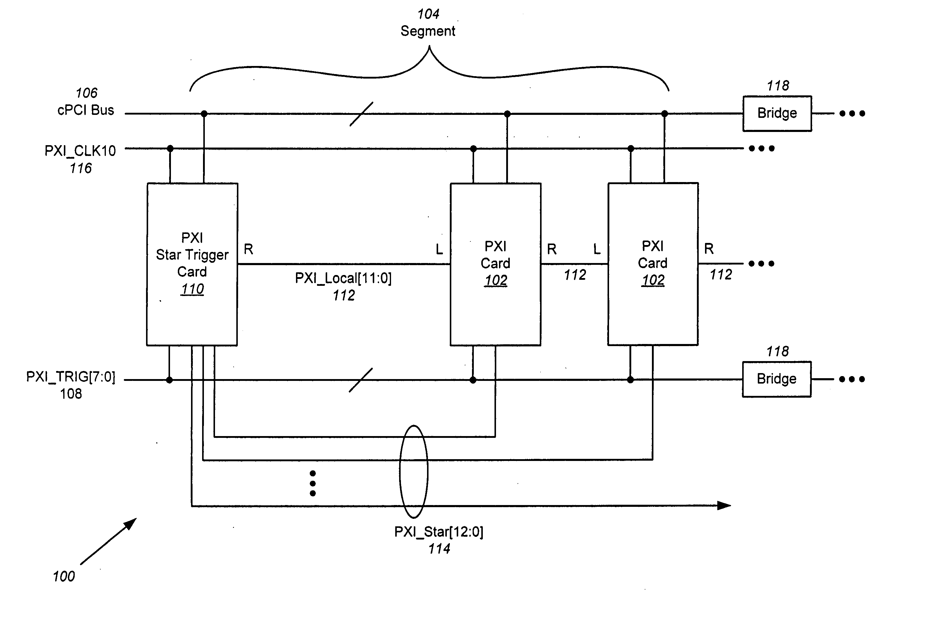
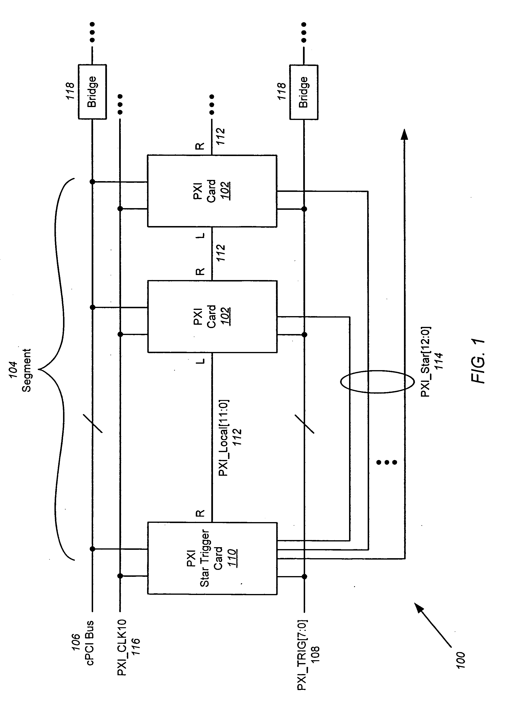
[0040] In particular, it should be noted that although embodiments of the present invention are described herein for use with a PXI chassis for purposes of illustration and explanation, other standardized test instrumentation chassis having standardized specifications and specification-compliant ports and backplanes fall within the scope of the present invention. For example, cPCI is similar to PXI, but with a slightly different form factor and bus structure.

[0041] Embodiments of the present invention are directed to providing precise timing control within a t...


PUM


Abstract

Precise timing control within a standardized chassis such as PXI is obtained by providing several control signals over PXI_LOCAL. A Least Common Multiple (LCM) signal enables all clocks to have coincident clock edges occurring at every LCM edge. A start sequence allows all PXI expansion cards in the test system to start at the same time. A MATCH line enables pincard modules to check for expected DUT outputs and either continue execution of their local test programs or loop back and repeat a section of the local test program in accordance with the result of the DUT output check. An End Of Test (EOT) line enables any one pincard module to abruptly end the local test programs running in all other pincard modules if an error is detected by the local test program in the pincard module.

Description

CROSS-REFERENCE TO RELATED APPLICATIONS [0001] This invention is related to U.S. Patent Application No. ______ entitled “Providing Precise Timing Control Within a Standardized Test Instrumentation Chassis,” filed ______, and U.S. Patent Application No. _______ entitled “Providing Precise Timing Control Between Multiple Standardized Test Instrumentation Chassis,” filed ______.FIELD OF THE INVENTION [0002] This invention relates to a test system for testing semiconductor devices such as integrated circuits (ICs), and more particularly, to providing the precise timing control needed for state-of-the-art Automatic Test Equipment (ATE) systems within a standardized test instrumentation chassis such as a Peripheral Component Interconnect (PCI) eXtensions for Instrumentation (PXI) chassis. BACKGROUND OF THE INVENTION [0003] A major reason for the high cost of conventional state-of-the-art ATE test systems is the specialized and complex nature of the ATE tester architecture. ATE tester manu...

Claims


Application Information

Patent Timeline
Patent Type & Authority Applications(United States)
IPC IPC(8): G01R31/02
CPCG01R31/31725G01R31/31726G01R31/319G01R31/28
Inventor LE, ANTHONYGOMES, GLEN
Owner ADVANTEST CORP
Why Eureka
Try Eureka