
Waffle sheet

a technology of waffle sheets and waffle sheets, applied in the field of waffle sheets, can solve the problems of inefficient baking time, burnt and distasteful surface, and high cost of baking

Inactive Publication Date: 2007-02-22
A LOACKER
View PDF18 Cites 12 Cited by
  • Summary
  • Abstract
  • Description
  • Claims
  • Application Information

AI Technical Summary

Benefits of technology

[0005] It is an object of the invention to make a wafer such that thick spots in the dough are largely avoided, the wafer can be uniformly cooked in the shortest possible baking time, and a uniform surface color is produced.
[0007] This is attained in that the support layer is formed as a corrugated layer of uniform thickness with both faces formed by straight lines that form a wavy or zig-zag line, the corrugation valleys of one face of the corrugated layer and the corrugation valleys of the other face reach to or overlap an imaginary center line in the cross section, the ribs have an average wall thickness corresponding to the thickness of the corrugated layer and extend at an angle or perpendicular to corrugation crest lines, and bridge the valleys preferably to the same depth, and the ribs of one face are offset from the ribs of the other face. It is significant that there is not the standard planar core layer as in the above-described wafers that causes the most buildup of batter. Overlapping crests of a corrugated or zig-zag shaped core layer are distinctly different according to the invention from a planar core layer. The overlapping of the crests enures that there is no throughgoing planar core layer serving as support layer. In an extreme case it is possible for the corrugation crests to touch a center line in the cross section of the wafer in the recesses in the opposite face. The tightly zig-zag corrugated wafers are only strong in one direction. The strength in all planar directions is attributed to the thin ribs in the corrugation valleys. They form together with the crest lines of the corrugations an array of pockets. The pockets can be perfectly square, rectangular, triangular, or even rhombic or trapezoidal. Of course the ribs can be provided on both sides of the corrugated layer. Staggering of the ribs on opposite faces prevents dough buildup.
[0009] The wafers according to the invention can be used in many applications. The fine structure is particularly usable in the manufacture of candies with cream filling and coarser structures can be used as waffles for food. e.g. in combination with tasty coatings. A particularly distinguishing criteria is the batter content per unit of surface area of the wafer with no thick spots. According to use this can easily be changed with the wafer according to the invention.
[0010] To this end it is advantageous when to alter, that is increase or decrease, the batter content per unit of surface area of the wafer, by changing the angle, in particular between 45° and 75°, of the wave or zig-zag line of the corrugated layer forming the support layer to the imaginary center line with generally uniform wall thickness. It is also possible to alter, that is increase or decrease, the batter content per unit of surface area of the wafer, by varying the radius of curvature, in particular between 0.6 mm and 2 mm, at the crests of the corrugations with generally unchanged wall thickness and inclination angle.

Problems solved by technology

If the baking temperature is made higher, the thicker dough regions are baked through, but the wafer is elsewhere too dark, and its surface is burnt and distasteful.
If the baking temperature is lowered, the baking time increases disproportionately in a very inefficient manner, e.g. from 1 minute to 3 minutes.

Method used


Image

  • Waffle sheet
  • Waffle sheet
  • Waffle sheet

Examples


Embodiment Construction

[0013] A wafer is made by pouring liquid batter into a heatable baking mold comprised of two plates whose faces form the upper and lower faces of the wafer. The baking mold is closed by snugly interfitting the plates with the dough between them. Only a steam vent opens to the outside so that steam created inside by the baking operation can escape. The wafer is baked under pressure. The wafers are made individually, one after the other.

[0014] In a continuous method the dough is rolled out and continuously run through a fryer so the product lacks the desired structural detail and low moisture content.

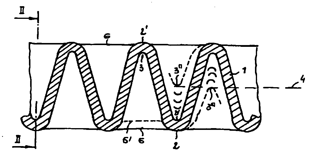
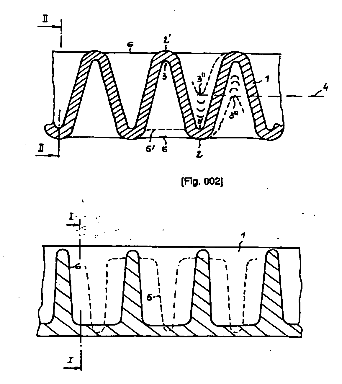
[0015] The wafer is comprised according to FIGS. 1 and 2 of a tightly wavy layer that is here termed a corrugated layer 1. This corrugated layer 1 is of uniform thickness throughout. For example the thickness is 0.6 to 2 mm and the corrugations are spaced at 3 to 5 mm. The corrugations extends along a zig-zag path which can be nearly sinusoidal. Corrugation crests 2 and 2′ and valleys 3...


PUM


Abstract

Disclosed is a waffle sheet as a long-life baked product, comprising one respective rib structure on opposite surfaces of a support layer. Said support layer has the shape of a corrugated plate (1, 10, 11, 12), e.g. with a sinusoidal or angular, trapezoidal undulation, the walls of said corrugated plate having the same thickness. Ribs (5, 5′, 6) which penetrate or bridge the wave troughs (3, 3′, 3″, 3′″) extend transversal to said undulation. The wave troughs (3, 3′, 3″, 3′″) of both surfaces or the top face and bottom face touch or penetrate an imaginary center line (4) of the cross-section of the waffle. The average wall thickness of the ribs (5, 5, 6) corresponds to the wall thickness of the corrugated plate (1, 10, 11, 12). The ribs (5, 5′, 6) extend at an angle from or perpendicular to the apex line of the waves. The ribs (6) in the wave troughs (3, 3′) located on the top face are offset by half a separation relative to the ribs (5, 5′) of the wave troughs (3, 3′″) located on the bottom face. The angles (α, α′) of the zigzag-type undulation (14) or the radii of curvature (r, r′) can be varied according to the amount of dough used per spatial unit. Also disclosed is a baking mold (13) comprising vapor bars (15) at the periphery thereof, said vapor bars (15) being provided with vapor slots on the undulation (14) which tapers as a slot.

Description

TECHNICAL BACKGROUND [0001] The invention relates to a wafer as a durable baked good that has ribs on both sides and that is shaped in a mold between a pair of planar structured outer baking plates and is there baked into a stable shape, the ribs of the rib structure extending from both faces of a support layer. In addition the invention relates to a heatable baking mold for making such a wafer. [0002] Wafers are preferably layered together to make cream-filled pieces and form a multilayer product. They are also encased with chocolate and in single or multiple layers constitute a fine snack. Each such wafer has as a support layer a planar middle layer made from dough forming the core layer that carries the rib structure constructed as a field of square pockets. This rib structure is provided on both sides of the core layer. The rib squares can be staggered from one side to the other side by half the rib spacing. [0003] The formation of the core layer leads to a buildup of dough unde...

Claims


Application Information

Patent Timeline
IPC IPC(8): A21D13/00A21D8/06A21D13/08A23L19/12
CPCA21D13/80A21D8/06
Inventor HAAS, FRANZ
Owner A LOACKER
Learn More