Method for monitoring the performance reliability of a control unit and diagnostic device

a technology for diagnostic devices and control units, applied in the direction of process and machine control, pedestrian/occupant safety arrangement, instruments, etc., can solve the problems of control units and/or sensors that cannot function or function properly, impact may damage control units and/or sensors as well, and so as to minimize the risk of a control unit or a sensor failing in a crash and minimize the repair costs resulting from a crash

Inactive Publication Date: 2007-02-22
ROBERT BOSCH GMBH
View PDF11 Cites 9 Cited by
  • Summary
  • Abstract
  • Description
  • Claims
  • Application Information

AI Technical Summary

Benefits of technology

[0012] The principle on which the present invention is based is that the control unit or a comparable device decides on its own whether the control unit should be exchanged in the aftermath of a crash. In addition or as an alternative, the control unit or a comparable device may also decide whether and, if so, which s

Problems solved by technology

As is often the case in electronic devices, there is the risk in control units and/or in sensors as well that they will not function or will not function properly, Which, however, must be avoided under all circumstances when safety devices are involved.
In control units for safety devices for the protection of vehicle occupants and their remote sensors there is also always the risk that they get damaged in a crash.
If the impact, and thus the deformation, is severe enough to deform the location at which the control unit or the appropriate sensors is affixed, the impact may have damaged the control unit and/or the sensors as well.
Such damage may be so severe that the control unit or the sensors are no longer operable.
Furthermore, it is possible that the control device or the sensors have indeed been damaged

Method used


Image

  • Method for monitoring the performance reliability of a control unit and diagnostic device
  • Method for monitoring the performance reliability of a control unit and diagnostic device
  • Method for monitoring the performance reliability of a control unit and diagnostic device

Examples


Embodiment Construction

[0024] Unless specifically mentioned otherwise, identical or functionally equivalent elements have been provided with matching reference numerals in the figures of the drawing.

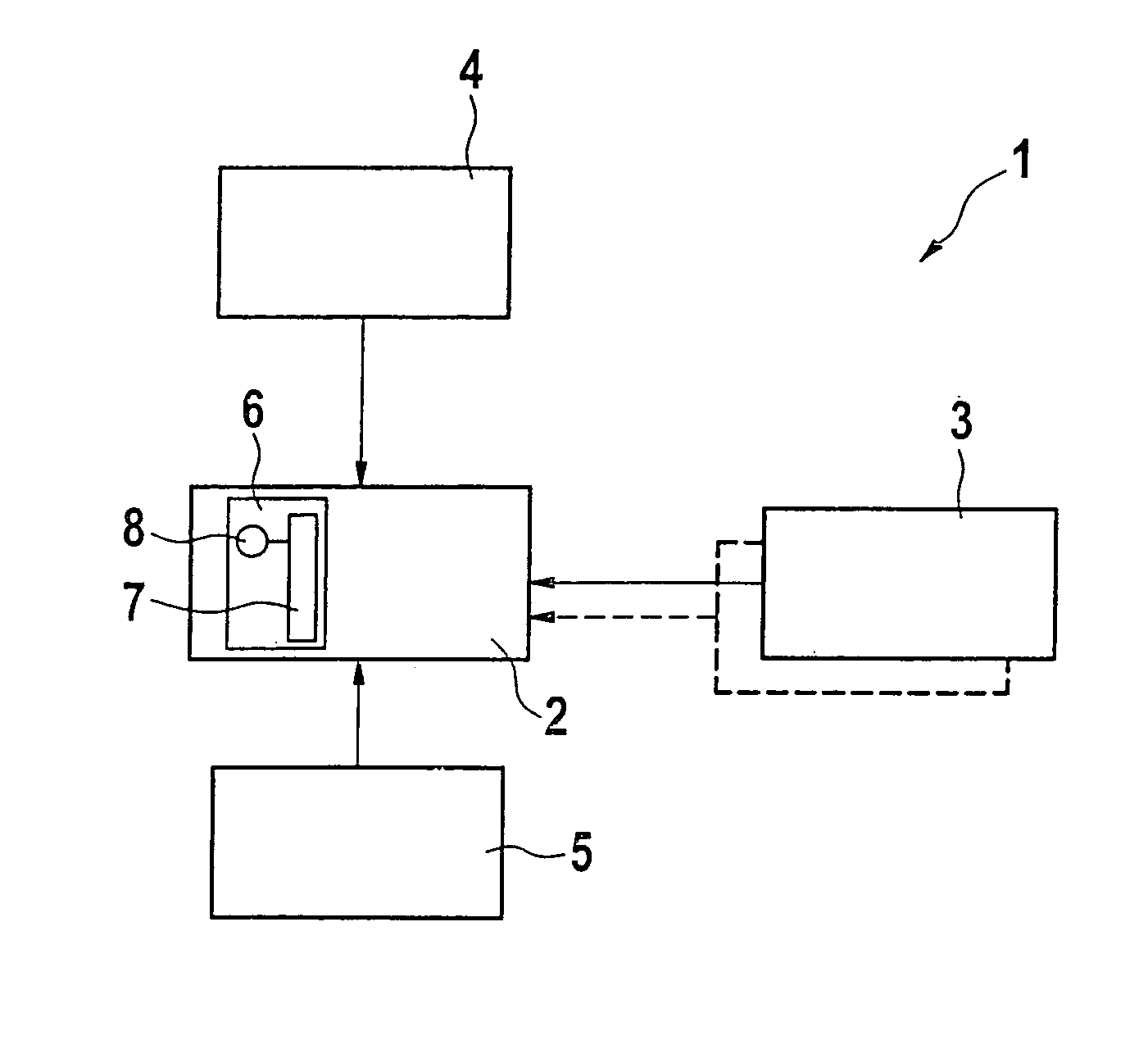
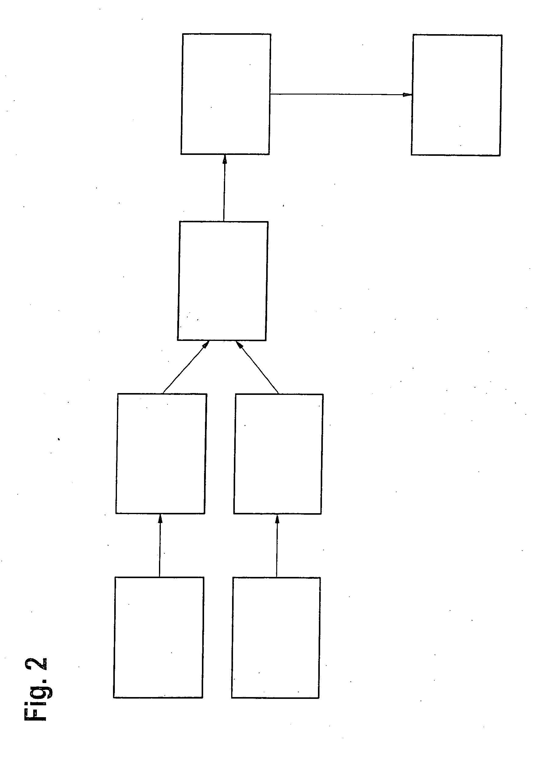
[0025]FIG. 1 shows the block diagram of a safety device having the diagnostic device according to the present invention.

[0026] Reference numeral 1 in FIG. 1 denotes the safety device. Here, safety device 1 is embodied as electronic restraining means, such as an airbag system. The safety device includes an airbag control unit 2 as well as a multitude of sensors 3 to 5. In the case at hand, safety device 1 has one or more front sensors 3 and side sensors 4, 5 although it is also possible to provide rear sensors as well. The present invention includes a diagnostic device 6. Diagnostic device 6 communicates bidirectionally, both with control unit 2 and sensors 3 to 5. Instead of a single diagnostic device 6 it would also be conceivable, of course, to provide each control unit 2 or each sensor 3 to 5 with its own...


PUM


Abstract

The present arrangement provides a method for monitoring the performance reliability of a control unit and/or at least one sensor of a safety device for the protection of vehicle occupants, comprising the steps that a negative acceleration or velocity caused by an impact, in particular, be recorded; a value for the impact severity be derived from the recorded acceleration or velocity; and the value for the impact severity be compared to a predefined threshold value. If the value for the impact severity exceeds the predefined threshold value, an error-function signal will be output, which indicates that the proper functioning can no longer be ensured for the control unit and/or for at least one sensor. The present arrangement also relates to a diagnostic device for such a method.

Description

FIELD OF THE INVENTION [0001] The present invention relates to a method for monitoring the performance reliability of a control unit and / or at least one sensor of a safety device for the protection of vehicle occupants, as well as a diagnostic device. BACKGROUND OF THE INVENTION [0002] Safety devices for the protection of vehicle occupants such as front and side airbags, rollover bars, belt tighteners etc., are standard equipment in motor vehicles manufactured these days. Typically, such safety devices are made up of a multitude of sensors for detecting a crash by recording a crash-related negative acceleration or velocity, and a control unit for the safety device, which analyzes a value derived from the crash. If a specific threshold value, which points to the presence of a crash, is detected, the control unit triggers the corresponding restraining means. [0003] As is often the case in electronic devices, there is the risk in control units and / or in sensors as well that they will n...

Claims


Application Information

Patent Timeline
IPC IPC(8): G01M17/00G06F19/00B60R21/01B60R21/0132B60R21/0136B60R21/015
CPCB60R21/013B60R21/0132B60R21/0136B60R21/0156B60R21/01562B60R2021/01322
Inventor MEISSNER, PETER
Owner ROBERT BOSCH GMBH
Why Eureka
Try Eureka