Method of assembling a turbomachine

a turbomachine and cylinder body technology, applied in the field of turbomachines, can solve the problems of high bearing damage risk, inability to fit the lp turbine, and the retaining nut of the outer ring and the ring, so as to improve the assembly conditions of the lp turbine and reduce the risk of damag

Active Publication Date: 2007-03-01
SN DETUDE & DE CONSTR DE MOTEURS DAVIATION S N E C M A
View PDF8 Cites 23 Cited by
  • Summary
  • Abstract
  • Description
  • Claims
  • Application Information

AI Technical Summary

Benefits of technology

[0008] The objective of the invention is to improve the assembly conditions of LP turbines on an engine of the type described above in order to reduce the risks of damaging the inter-shaft bearing.
[0017] By controlling the centering of the shaft with respect to the journal, correct positioning is guaranteed, which allows, once the journal is expanded, trouble-free mating. Moreover, the heating of the journal from the outside frees space allowing the engagement of the shaft and consequently reduces the assembly time.

Problems solved by technology

This operation comprises high risks of damage to the bearing if the conditions are not controlled.
The highest risk for the bearing is a hard contact between the rollers and the retaining nut of the outer ring and the ring itself.
At present, the means used do not make it possible to fit the LP turbine without risk to this inter-shaft bearing, because of the heating method used and of the imprecise positioning of the LP turbine.
The investigations carried out on this operating method have revealed several disadvantages: a relatively high heterogeneity, of the order of 20° C., of the temperature levels of the heated parts, a high risk of adding pollution by the ambient air taken for the heating and the heating device itself, and a high risk of damage of the outer ring of the bearing by contact with the diffuser.
This risk is particularly high as the clearance between the diffuser and the outer ring is only a few millimeters, and the assembly is installed on rollers and therefore presenting a risk of being moved inadvertently by the operators.

Method used


Image

  • Method of assembling a turbomachine
  • Method of assembling a turbomachine
  • Method of assembling a turbomachine

Examples


Embodiment Construction

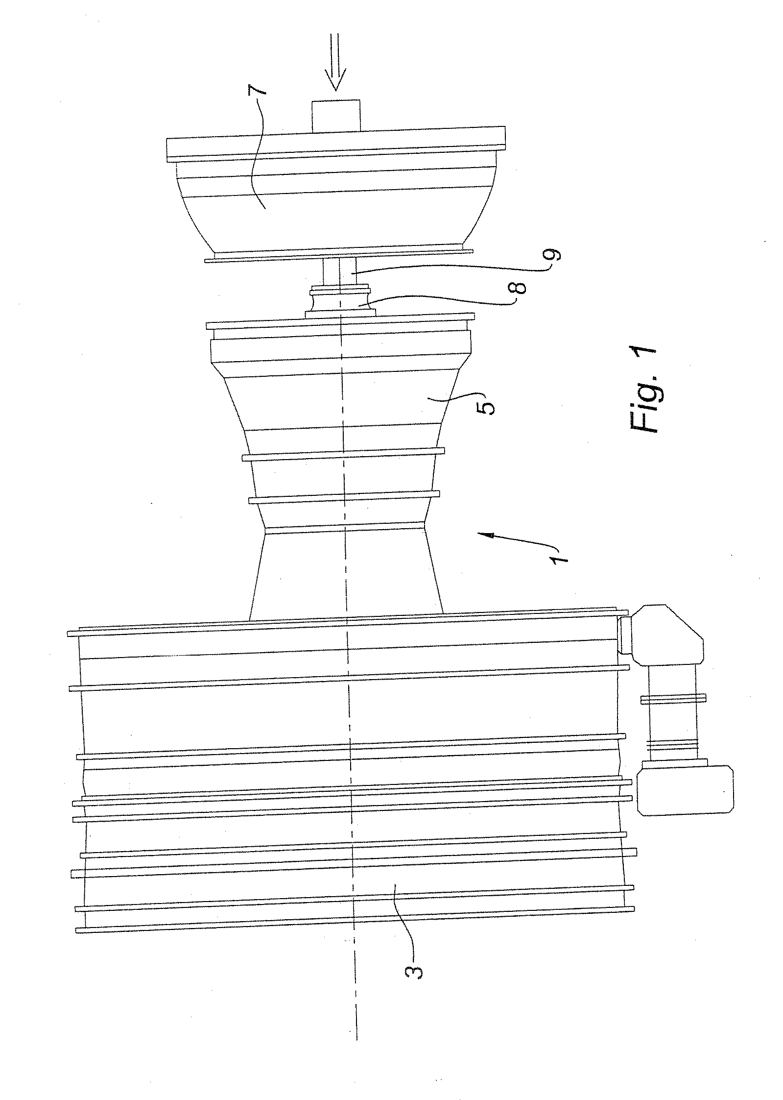
[0034]FIG. 1 shows an engine in the process of assembly in which only the outer casings are seen. In this case it is a double-body bypass turbojet such as the CFM56. It comprises a front fan 3 and a module 5, called the first module, constituted by the HP body with its shaft, called the first shaft. These components are already assembled. In this view the LP turbine module 7, called the second module, whose shaft 9, called the second shaft, is already engaged in the HP body, is in the process of being fitted. The critical zone is situated in zone 8 of the inter-shaft bearing whose visibility is zero.

[0035] In the continuation of the description, the fitting of this second module, the low pressure module, into the first module, the high pressure module, is therefore described.

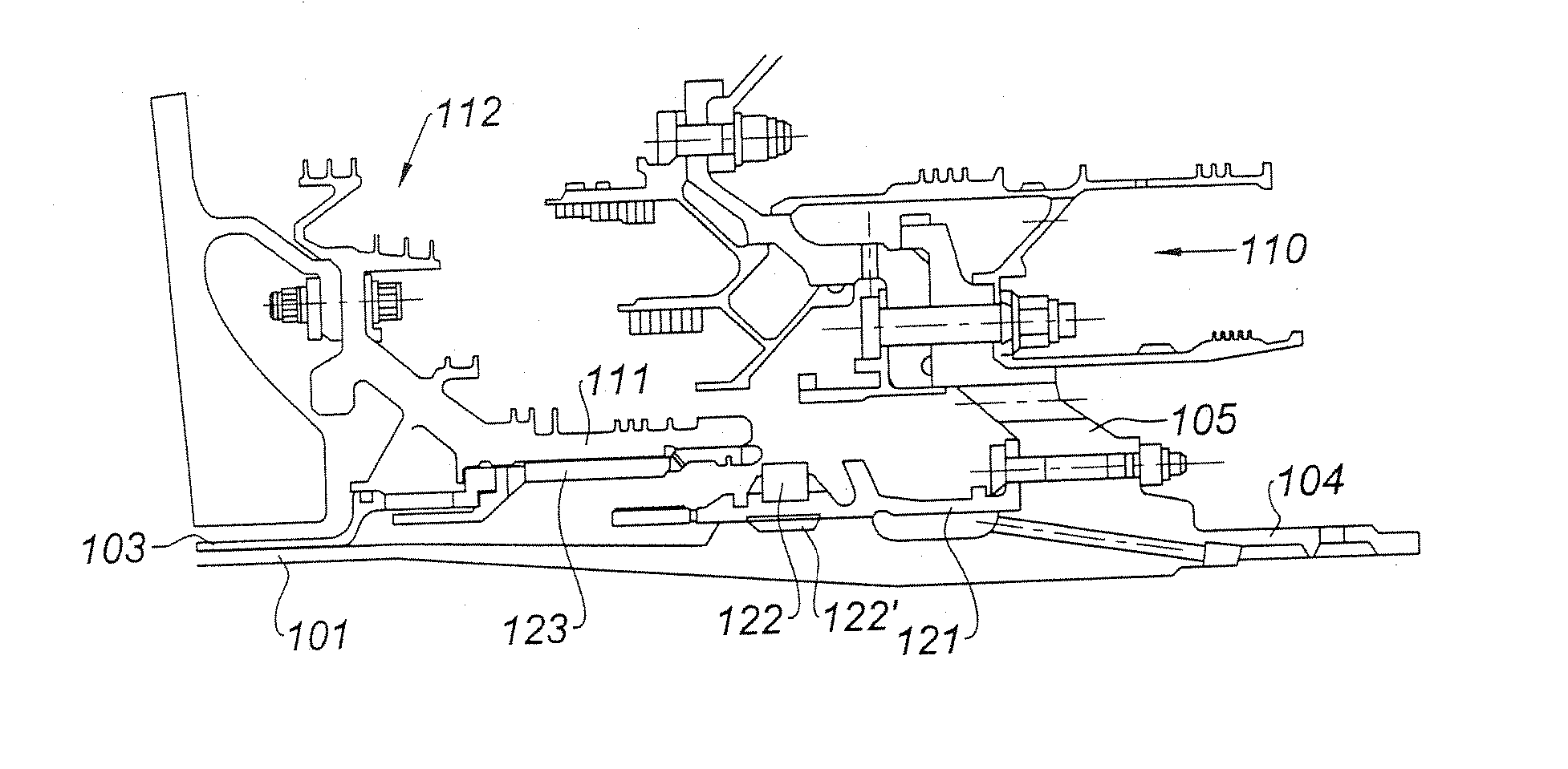
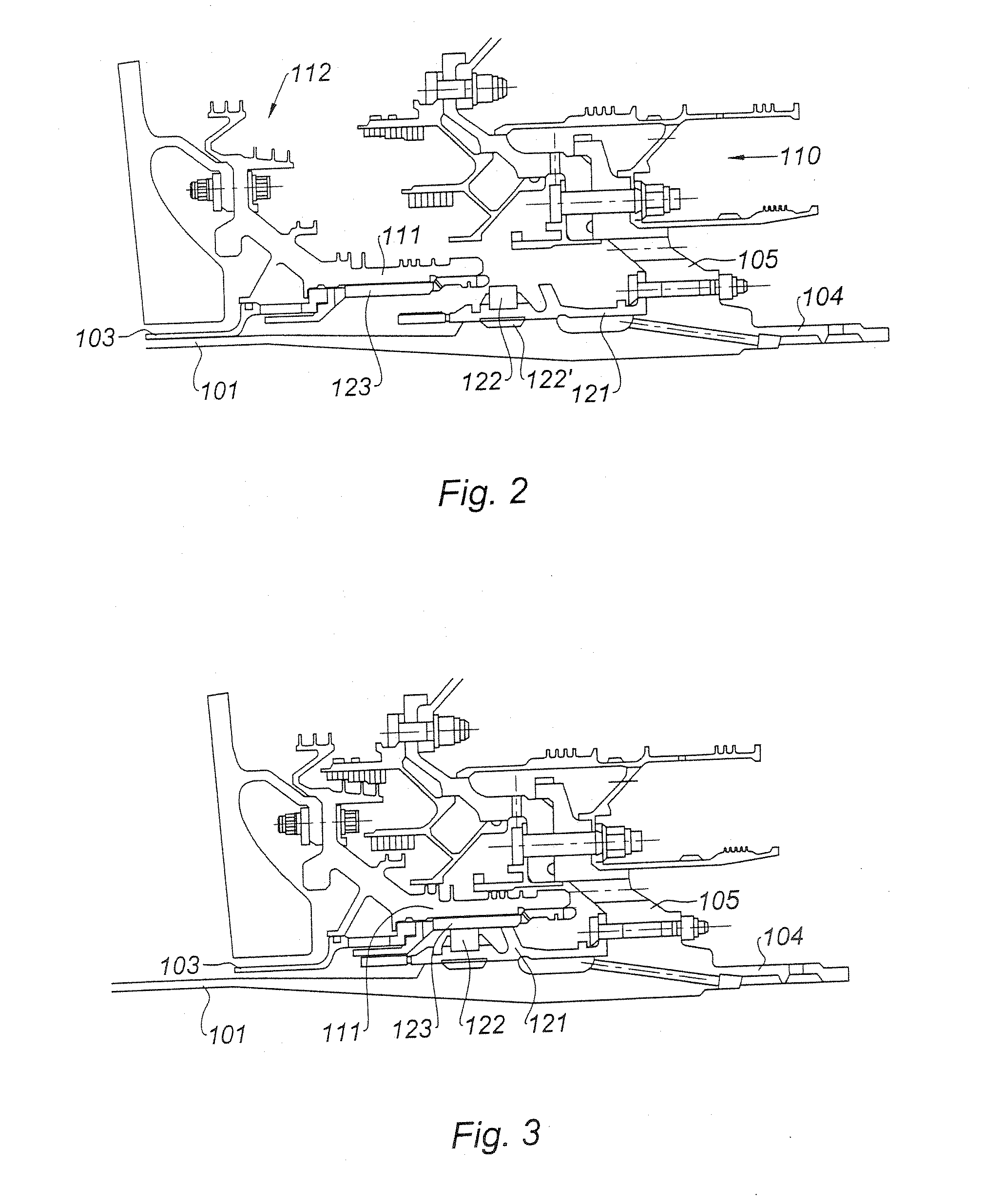
[0036] In FIG. 2, this zone is seen in cross-section and in greater detail. The shaft 101, the second shaft of the second module, the LP turbine, is housed in the shaft 103, the first shaft, of the first modul...


PUM

PropertyMeasurementUnit
temperatureaaaaaaaaaa
distanceaaaaaaaaaa
pressureaaaaaaaaaa

Abstract

The invention relates to a method of assembly of a turbomachine, in particular of a gas turbine engine, comprising at least a first module and a second module a second shaft assembled by a bearing, said bearing comprising an outer ring shrink-fitted inside a journal integral with the first module and an inner ring integral with the second shaft, according to which the second module is assembled on the first module by engagement of the second shaft, with said inner ring, inside the journal comprising said outer ring, wherein it comprises the following steps: mating the second module with the second shaft up to a determined distance from the journal, centering the second shaft with respect to the journal, said centering being controlled on the basis of measuring distance deviations with respect to a reference on the journal, expansion of the journal by heating its outer surface, completion of the mating of the second shaft.

Description

BACKGROUND OF THE INVENTION [0001] The present invention relates to the field of turbomachines and relates more particularly to multibody gas turbine engines. It relates to engine assembly operations and in particular to the fitting of the low pressure turbine module to a high pressure body. DESCRIPTION OF THE PRIOR ART [0002] A turbojet with a front turbofan and a double body, for example, comprises a low pressure (LP) body and a high pressure (HP) body. The LP body rotates at a first speed and the LP turbine drives the fan. The HP body rotates at a speed different from that of the LP turbine. The shafts of the two bodies are concentric, the low pressure shaft is guided in rotation in bearings supported by the fixed structure of the engine, respectively situated downstream of the turbine and upstream of the high pressure compressor. The shaft of the high pressure body is guided in rotation by bearings supported by the fixed structure of the engine upstream and by the shaft of the l...

Claims


Application Information

Patent Timeline
Patent Type & Authority Applications(United States)
IPC IPC(8): B23P15/04
CPCF01D5/026F01D25/285F02C7/20F05D2230/642Y10T29/49316Y10T29/49329Y10T29/4932Y10T29/49826Y10T29/49321Y10T29/49865Y10T29/49327Y10T29/4933
Inventor BERGEROT, FRANCOIS PIERRE ANDRELEEDER, LAURENTMALTERRE, JACQUES PIERRE FELIXSOUART, BERNARD ADRIEN EDMONDTHOMAS, HUBERT
Owner SN DETUDE & DE CONSTR DE MOTEURS DAVIATION S N E C M A
Why Eureka
Try Eureka