Aircraft evacuation slide with primary gas relief valve

a technology for aircraft and gas relief valves, which is applied in the direction of aircraft ejection means, operating means/releasing devices of valves, weapons, etc., can solve the problems of sagging evacuation, melting or scorching of fabric, and passengers being removed, so as to increase the volume of gas and increase the slide length

Active Publication Date: 2007-03-01
THE BF GOODRICH CO
View PDF11 Cites 28 Cited by
  • Summary
  • Abstract
  • Description
  • Claims
  • Application Information

AI Technical Summary

Benefits of technology

[0007] The present invention comprises a control valve having a normally-open vent that closes after a predetermined period of time calculated to vent the required excess gas. According to an embodiment of the invention, the control valve comprises an inlet port in fluid communication with the pressure vessel containing the stored inflation gas, a primary valve member closing the inlet port, a primary outlet port in fluid communication with the inflatable evacuation slide and a chamber leading from the inlet port to the primary outlet port. The chamber includes a gas release outlet that is normally-open. In operation, in the event of an aircraft emergency exit door being opened in the “armed” condition,

Problems solved by technology

Emergencies at take-off and landing often demand swift removal of passengers from the aircraft because of the potential for injuries from fire, explosion, or sinking in water.
Pyrotechnic gas generators have an advantage in that they are small, lightweight, and produce a high volume of gas, however, the high temperature gas produced by a gas generator alone can cause numerous problems including sagging of the evacuation slide as the inflation gas cools and, in some cases melting or scorching of the fabric out of which the inflation slide is fabricated.
Use of stored compressed gas by itself, although simple, implicates a weight penalty that must be paid for carrying a pressure vessel having sufficient capacity (in terms of volume and pressure) to inflate the evacuation slide over the wide operational temperature range speci

Method used


Image

  • Aircraft evacuation slide with primary gas relief valve
  • Aircraft evacuation slide with primary gas relief valve
  • Aircraft evacuation slide with primary gas relief valve

Examples


Embodiment Construction

[0012] The drawing figures are intended to illustrate the general manner of construction and are not necessarily to scale. In the detailed description and the drawing figures, specific illustrative examples are shown and herein described in detail. It should be understood, however, that the drawing figures and detailed description are not intended to limit the invention to the particular form disclosed, but are merely illustrative and intended to teach one of ordinary skill how to make and / or use the invention claimed herein and for setting forth the best mode for carrying out the invention.

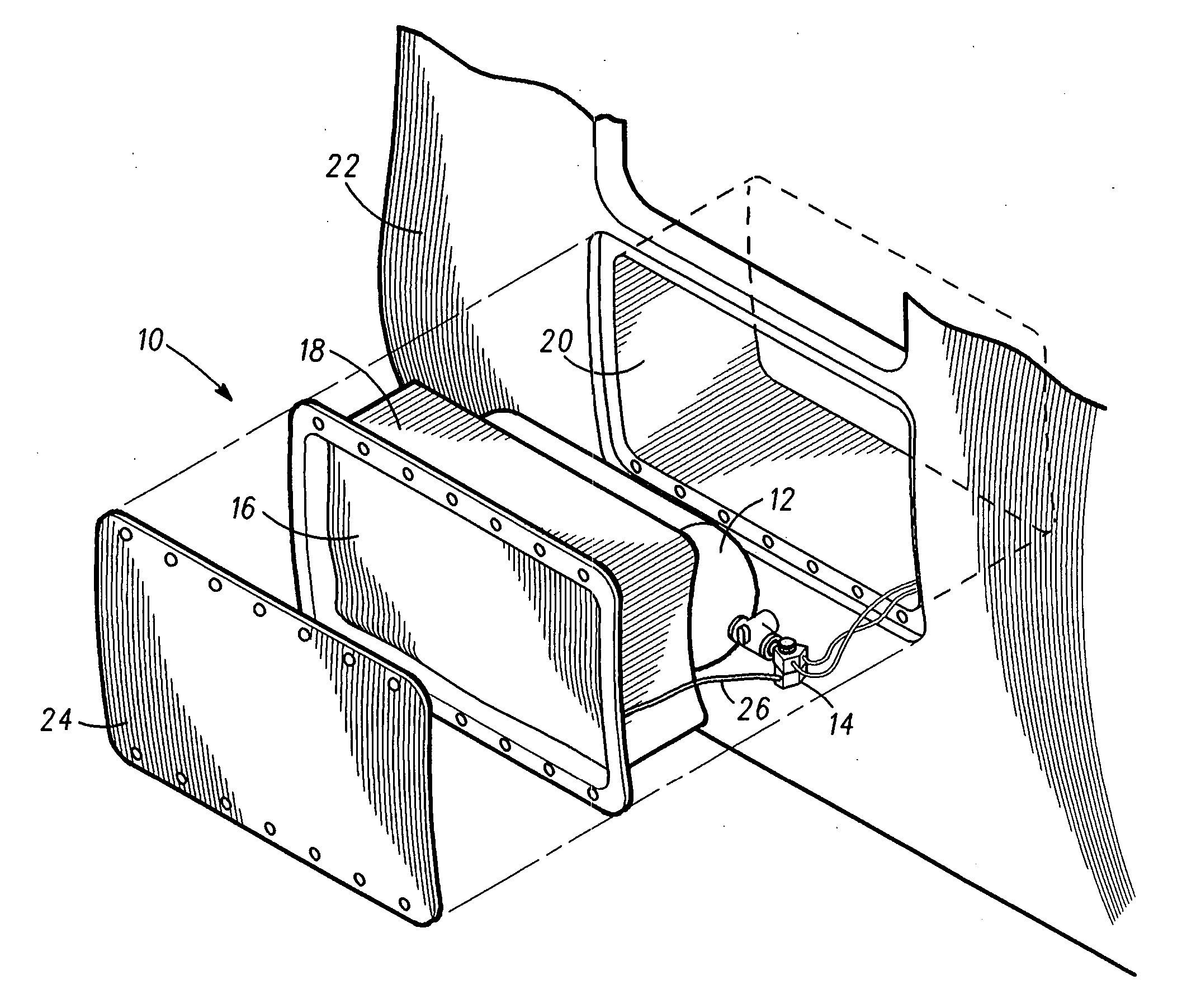
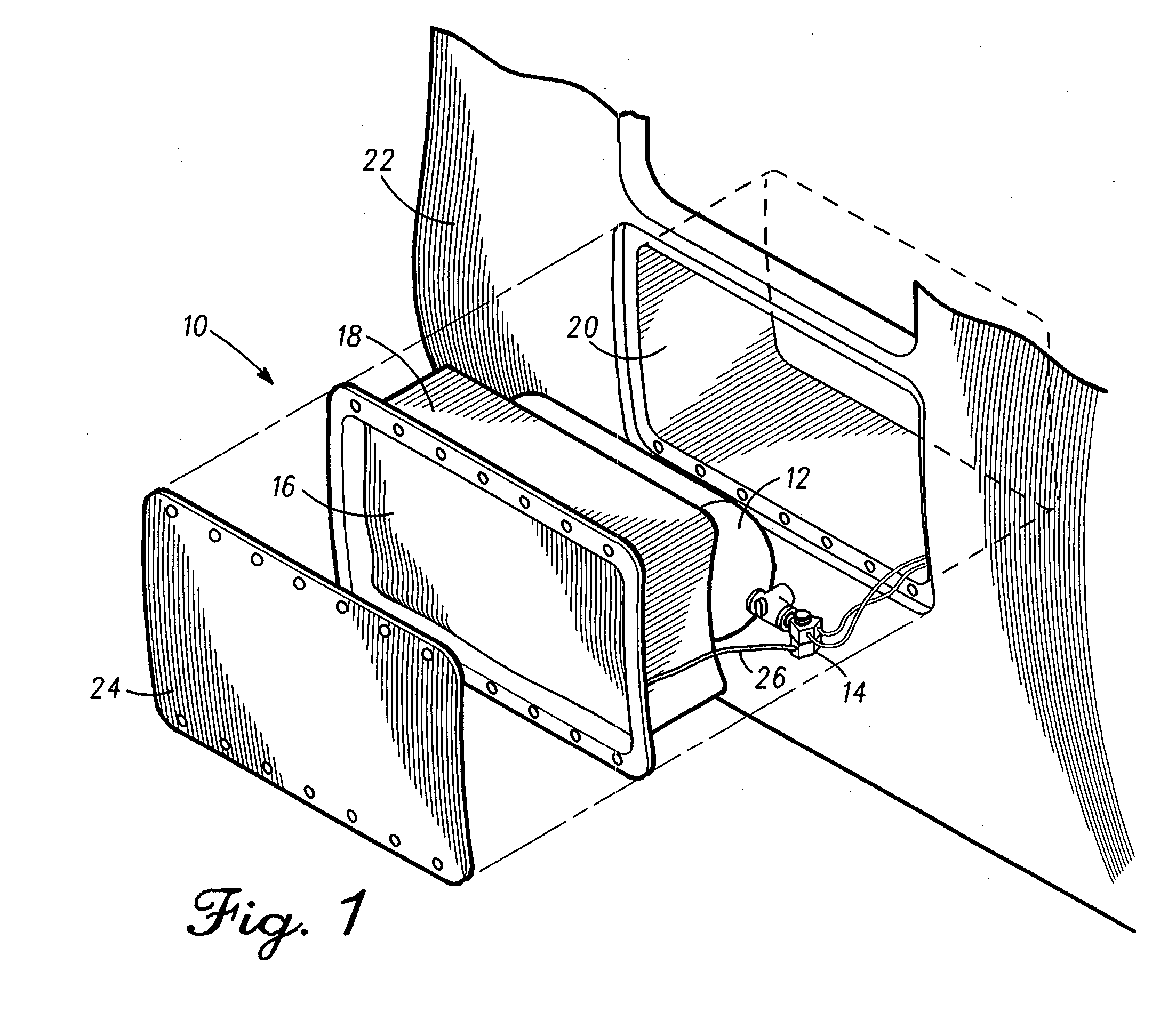
[0013] With reference to FIG. 1, an inflatable aircraft evacuation slide system 10 incorporating features of the present invention comprises a pressure vessel 12 containing pressurized inflation gas, a control valve 14 and an inflatable evacuation slide 16 stored in an uninflated condition within in a packboard compartment 18. Packboard compartment 18 is secured within a recess 20 in the outer h...


PUM


Abstract

An emergency evacuation slide system includes a control valve having a normally-open vent that closes after a predetermined period of time calculated to vent excess inflation gas produced by the gas generator. In operation, in the event of an aircraft emergency exit door being opened in the “armed” condition, the primary valve member of the control valve is opened allowing inflation gas to flow into the valve chamber. A portion of the gas entering the chamber is vented through the normally-open vent. After a predetermined period of time calculated to be sufficient to vent the excess inflation gas, the normally-open valve is closed to divert 100% of the remaining inflation gas into the evacuation slide.

Description

BACKGROUND OF THE INVENTION [0001] This invention relates to emergency evacuation equipment for aircraft, in particular to an inflation device for inflating an inflatable aircraft evacuation slide or other inflatable device. [0002] The requirement for reliably evacuating airline passengers in the event of an emergency is well known. Emergencies at take-off and landing often demand swift removal of passengers from the aircraft because of the potential for injuries from fire, explosion, or sinking in water. A conventional method of quickly evacuating a large number of passengers from an aircraft is to provide multiple emergency exits, each of which is equipped with an inflatable evacuation slide. Current state of the art emergency evacuation slide systems comprise an inflatable evacuation slide that is stored in a folded, uninflated state together with a source of inflation gas. The source of inflation gas typically comprises a gas generator, stored compressed gas, or a combination th...

Claims


Application Information

Patent Timeline
IPC IPC(8): B64C1/22
CPCF16K31/122B64D25/14Y10T137/86324
Inventor CLEGG, ANDREWWHITTINGHAM, DAVID M.SEABASE, PETER P.
Owner THE BF GOODRICH CO
Why Eureka
Try Eureka