Lundell type rotor core structure and rotary electric machine employing the same

a technology of rotor core structure and electric rotary machine, which is applied in the direction of dynamo-electric machines, magnetic circuit rotating parts, and shape/form/construction of magnetic circuits, etc., can solve problems such as magnetic sound output, and achieve the effect of suppressing magnetic sound and simplifying structur

Inactive Publication Date: 2007-03-01
DENSO CORP
View PDF22 Cites 44 Cited by
  • Summary
  • Abstract
  • Description
  • Claims
  • Application Information

AI Technical Summary

Benefits of technology

[0024] With such a structure set forth above, the electromagnetic gap can have a magnetic field pattern that is made closer to a sine wave, enabling the suppression of the magnetic sound in a simplified structure.

Problems solved by technology

This results in vibration of the teeth at high frequencies to cause a magnetic sound to be output.

Method used


Image

  • Lundell type rotor core structure and rotary electric machine employing the same
  • Lundell type rotor core structure and rotary electric machine employing the same
  • Lundell type rotor core structure and rotary electric machine employing the same

Examples


Embodiment Construction

[0034] A Lundell type rotor core structure of a rotary electric machine according to the present invention is described below in detail with reference to the accompanying drawings. However, the present invention is construed not to be limited to the embodiment described below and a technical concept of the present invention may be implemented in combination with other known technologies or the other technology having functions equivalent to such known technologies.

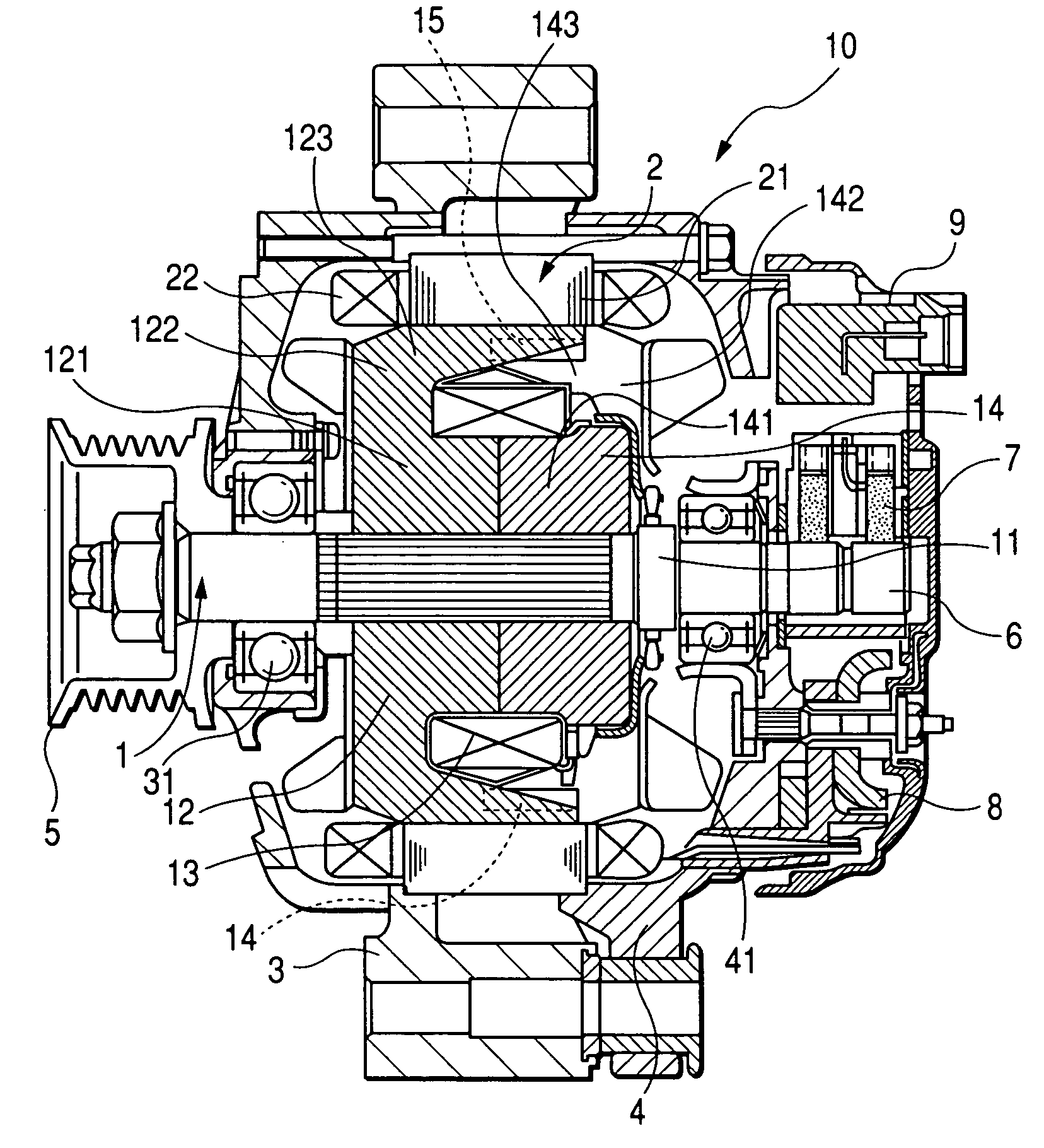
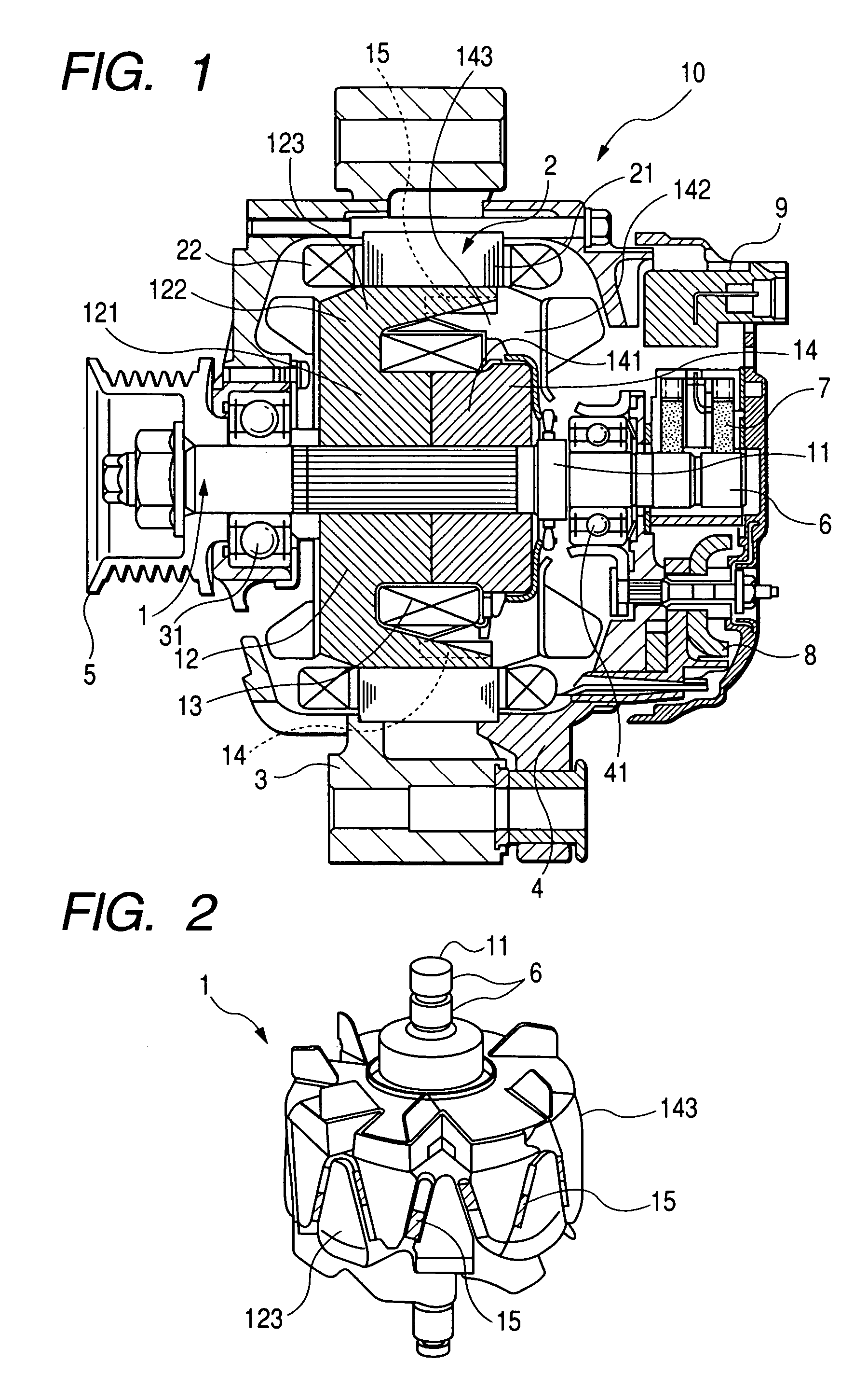
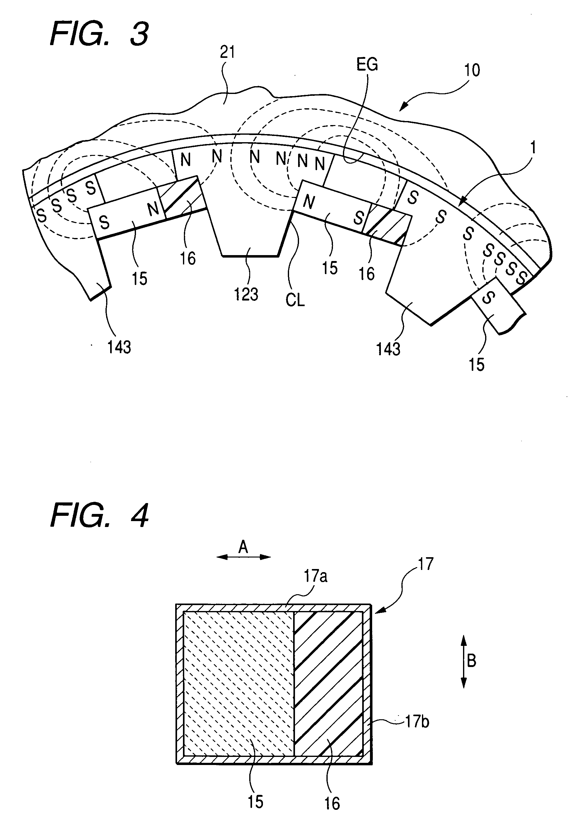
[0035]FIG. 1 shows a vehicle alternator, playing a role as an electric rotary machine, which has a Lundell-type rotor core structure of a first example according to the present invention. FIG. 2 is a perspective view of the rotor core structure incorporated in the vehicle alternator shown in FIG. 1 and FIG. 3 is an enlarged partial view showing the relationship between permanent magnets and associated claw pole portions of the rotor core structure shown in FIG. 2.

[0036] As shown in FIG. 1, the vehicle alternator 10 is co...


PUM


Abstract

A Lundell type rotor core structure and an electric rotary machine employing the same are disclosed. The rotor core structure has first and second claw pole portions alternately placed in a circumferential direction to define clearances each having a magnet mount position deviated from an axial center of each clearance and permanent magnets alternately disposed in the magnet mount positions of the clearances with respect to the axial direction of the rotor core structure for magnetizing the first and second claw pole portions in first and second magnetic polarities, respectively, wherein each of the permanent magnets allows a greater amount of magnetic fluxes to pass through one of the first and second claw pole portions than those passing through the other one of the first and second claw pole portions for minimizing harmonic component to suppress the magnetic sound.

Description

CROSS REFERENCE TO RELATED APPLICATIONS [0001] This application is related to Japanese Patent Application Nos. 2005-246249 and 2006-113507 filed on Aug. 26, 2005 and Apr. 17, 2006, respectively, the contents of which are hereby incorporated by reference. BACKGROUND OF THE INVENTION [0002] 1. Technical Field of the Invention [0003] The present invention relates to electric rotary machines of Lundell type rotors and, more particularly, to a Lundell type rotor core structure and an electric rotary machine employing such a Lundell type rotor core structure. [0004] 2. Description of the Related Art [0005] In general, a vehicular alternator includes a Lundell type rotor core that is comprised of a pair of pole cores each including a boss portion allowing magnetic fluxes to pass in an axial direction in an area radially inward of a field coil, a disc portion (column portion) extending radially outward from the boss portion at an axial end thereof for passing the magnetic fluxes of the magn...

Claims


Application Information

Patent Timeline
Patent Type & Authority Applications(United States)
IPC IPC(8): H02K1/22
CPCH02K21/044
Inventor ISHIZUKA, ATSUO
Owner DENSO CORP
Why Eureka
Try Eureka