Liquid crystal display device selectable between wide view angle display and narrow view angle display and liquid crystal display apparatus using same

a liquid crystal display and narrow view angle technology, applied in the direction of instruments, computing, electric digital data processing, etc., can solve the problems of difficult manufacture of view angle limiting devices, complicated structure of apparatus, narrow view angle of display images, etc., and achieve the effect of simple structur

Inactive Publication Date: 2007-03-01
CASIO COMPUTER CO LTD
View PDF2 Cites 25 Cited by
  • Summary
  • Abstract
  • Description
  • Claims
  • Application Information

AI Technical Summary

Benefits of technology

[0011] An object of the present invention is to provide a changeable view angle type liquid crystal display apparatus which has a simple structure and can perform wide view angle display and a narrow view angle display.

Problems solved by technology

Such a liquid crystal display apparatus limits the view angle of an image displayed by the liquid crystal display device, by applying a voltage between the electrodes of the view angle limiting device to reduce the visibility from an oblique observing direction.
Therefore, the display image of the liquid crystal display device cannot be recognized from the direction inclined to one side and from the direction inclined to the reverse side, and the view angle of the display image is seemingly limited and becomes narrow.
However, the view angle limiting device is hard to manufacture, because a complex aligning process (rubbing on aligning films) for imparting different directivities to each region has to be applied to the inner surfaces of the pair of substrates, in order to align the liquid crystal molecules of the liquid crystal layer in different alignment states region by region.
Further, a changeable view angle type liquid crystal display apparatus having the above-described view angle limiting device has to use two liquid crystal devices, thus has a problem that the apparatus becomes thick and its structure becomes complicated.

Method used


Image

  • Liquid crystal display device selectable between wide view angle display and narrow view angle display and liquid crystal display apparatus using same
  • Liquid crystal display device selectable between wide view angle display and narrow view angle display and liquid crystal display apparatus using same
  • Liquid crystal display device selectable between wide view angle display and narrow view angle display and liquid crystal display apparatus using same

Examples


first embodiment

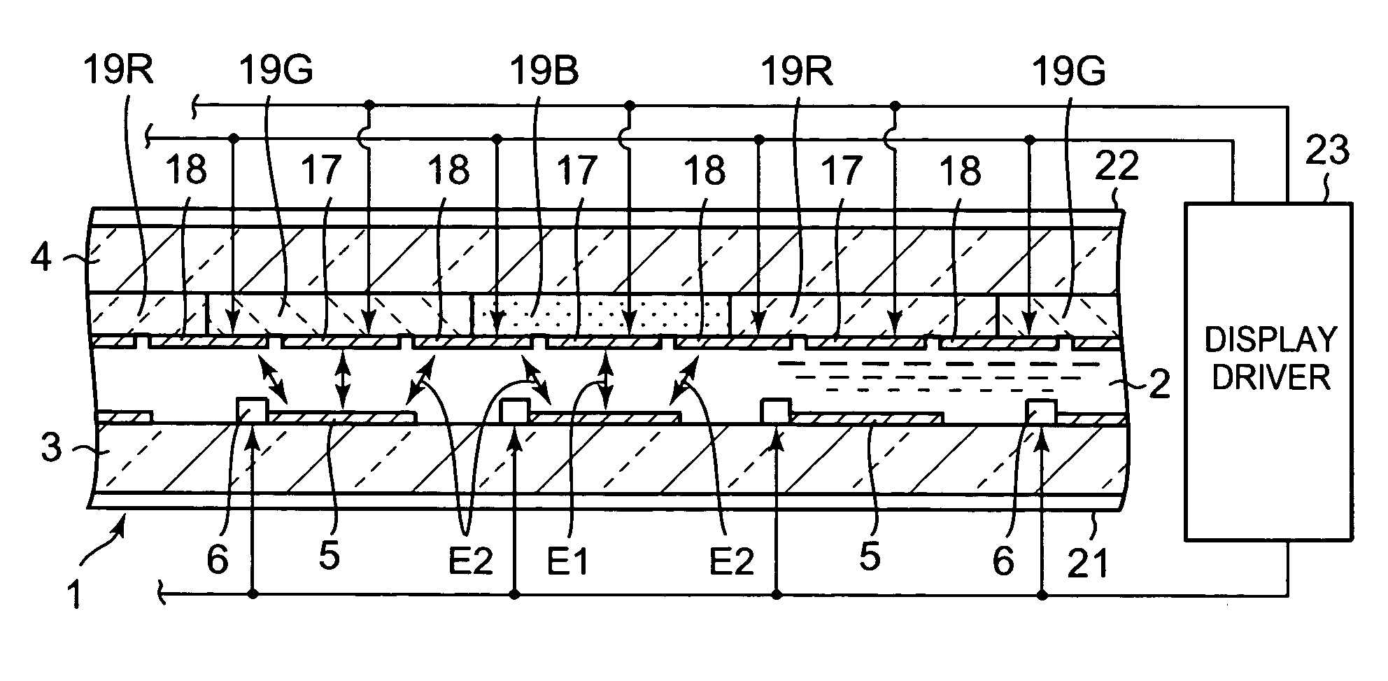
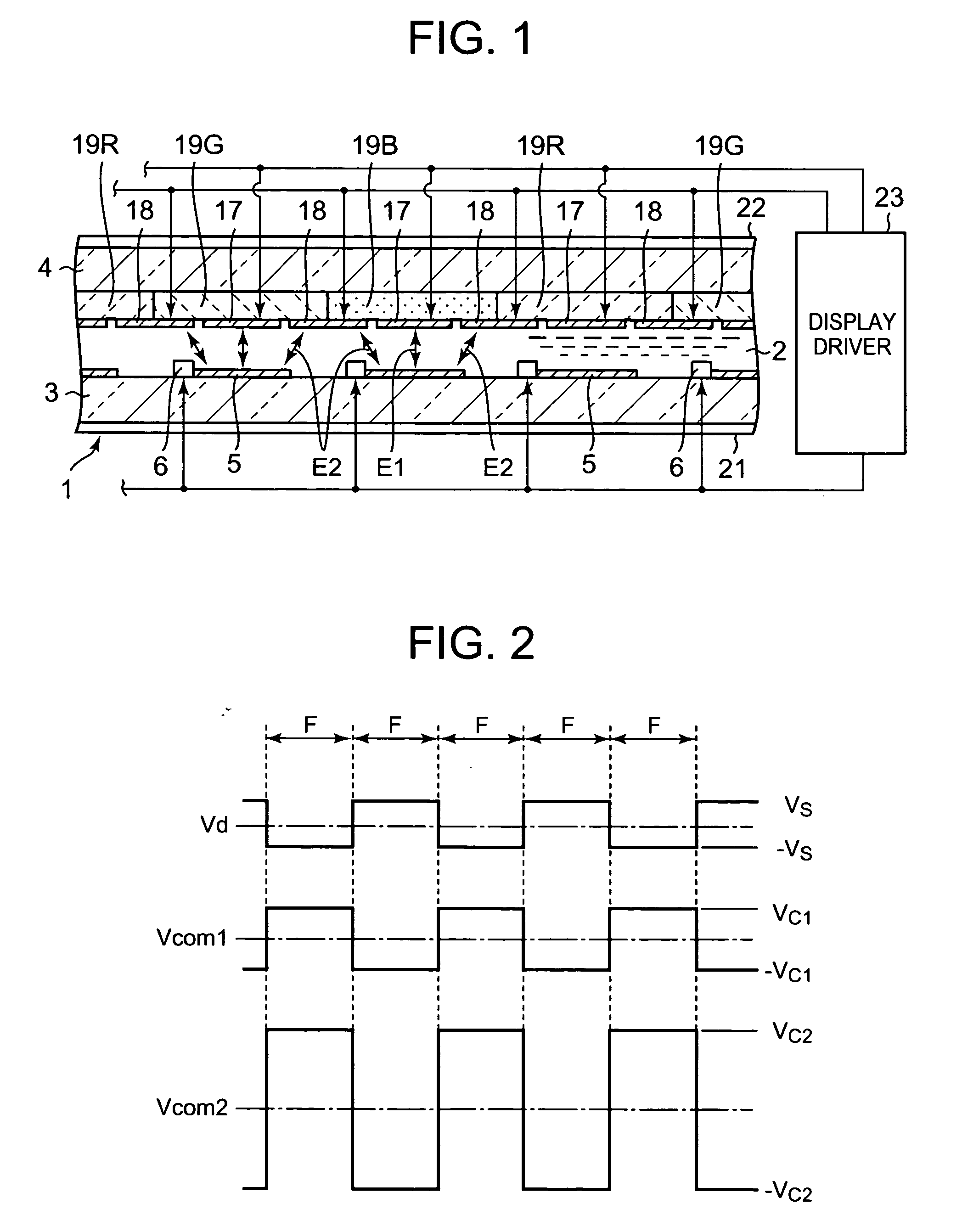
[0058]FIG. 1 to FIG. 6 show the present invention, and FIG. 1 is a cross sectional view showing the structure of a liquid crystal display apparatus and a schematic structure of a display driver.

[0059] The liquid crystal display apparatus is a changeable view angle type, and comprises a liquid crystal display device 1 which solely can perform both wide view angle display and narrow view angle display, and a display driver 23.

[0060] The liquid crystal display device 1 is an active matrix liquid crystal display device comprising an active element constituted by a thin film transistor (hereinafter referred to as TFT).

[0061] In the liquid crystal display device 1, one substrate 3 of a pair of transparent substrates 3 and 4 facing each other via a liquid crystal layer 2, has on its inner surface, a plurality of transparent pixel electrodes 5 arranged in a matrix of a row direction (left and right direction of the screen) and a column direction (up and down direction of the screen), a pl...

second embodiment

[0094]FIG. 7 shows the relationship among the plurality of pixel electrodes 5, the first and second opposing electrodes 17 and 18 and the color filters 19R, 19G, and 19B, according to the present invention.

[0095] According to the second embodiment, stripe-shaped color filters 19R, 19G, and 19B of three colors of red, green, and blue are formed on the inner surface of one of the pair of substrates 3 and 4, for example, the opposing substrate 4, such that the filters respectively correspond to a plurality of pixel electrode rows constituted by pixel electrode groups arranged in a direction perpendicular to the pixel electrode columns and have a length corresponding to the total length of the respective pixel electrode rows. According to this embodiment too, it is possible to display a color image having an excellent color quality both in case of wide view angle display and in case of narrow view angle display.

third embodiment

[0096]FIG. 8 shows the relationship among the plurality of pixel electrodes 5, the first and second opposing electrodes 17 and 18, and the color filters 19R, 19G, and 19B, according to the present invention.

[0097] According to the third embodiment, dot-shaped color filters 19R, 19G, and 19B of three colors of red, green, and blue which each have a width defined by one side edge of each filter that opposes to the center line of one of two regions between the pixel electrode columns which adjoin each other via one pixel electrode column, and by the other side edge of each filter that opposes to the center line of the other of the two regions between the pixel electrode columns, are formed on the inner surface of one of the pair of substrates 3 and 4, for example, the opposing substrate 4, such that the filters of the three kinds are arranged alternately in a mosaic pattern both in the direction of the pixel electrode columns and in the direction perpendicular to that direction, in ord...


PUM

PropertyMeasurementUnit
electric fieldaaaaaaaaaa
lengthaaaaaaaaaa
widthaaaaaaaaaa

Abstract

A liquid crystal display device has a plurality of pixel electrodes arranged in a matrix, a plurality of TFTs connected to the pixel electrodes respectively, and a plurality of gate lines and data lines, on the inner surface of one substrate of a pair of substrates facing each other via a liquid crystal layer. A first opposing electrode for forming, between itself and the plurality of pixel electrodes, a vertical electric field parallel with the direction of a normal line of the substrates, and a second opposing electrode for forming, between itself and the plurality of pixel electrodes, an oblique electric field obliquely inclined from the direction of the normal line are formed on the inner surface of the other substrate.

Description

BACKGROUND OF THE INVENTION [0001] 1. Field of the Invention [0002] The present invention relates to a changeable view angle type liquid crystal device which can select between wide view angle display and narrow view angle display, and a liquid crystal display apparatus using the same. [0003] 2. Description of the Related Art [0004] Since a liquid crystal display device has a wide view angle, its display might be seen by someone other than the viewer, from a direction inclined from the front forward direction. [0005] Hence, there has been proposed a liquid crystal display apparatus which limits the view angle of the liquid crystal display device by using a view angle limiting device, which is disposed on one surface of the liquid crystal display device, and whose area corresponding to the screen of the liquid crystal display device is divided into a plurality of regions to make the liquid crystal molecules in the respective regions aligned in different alignment states region by reg...

Claims


Application Information

Patent Timeline
Patent Type & Authority Applications(United States)
IPC IPC(8): G02F1/1343
CPCG02F1/1323G02F2201/122G02F2201/121G02F1/134336
Inventor TAKEI, JIRO
Owner CASIO COMPUTER CO LTD
Why Eureka
Try Eureka