Composite heat dissipating apparatus

Inactive Publication Date: 2007-03-01
DELTA ELECTRONICS INC
View PDF5 Cites 23 Cited by
  • Summary
  • Abstract
  • Description
  • Claims
  • Application Information

AI Technical Summary

Benefits of technology

[0014] As mentioned hereinabove, each of the heat sinks of the composite heat dissipating apparatus according to the invention is integrally formed, and the heat pipe is disposed in the space formed in the heat sinks. As the result, when the heat sinks are

Problems solved by technology

On the other hand, the working frequency of the electrical element is getting higher and higher, so that the heat generated by the switch loss due to the on/off switching operations of the transistor mainly increases the total heat of the electrical element.
If the heat is not dissipated properly, the operation speed of the chip is reduced, or even the lifetime of the chip is shortened.
As the result, this assembling method is not ideal under the considerations of the production efficiency and the electroplating cost

Method used


Image

  • Composite heat dissipating apparatus
  • Composite heat dissipating apparatus
  • Composite heat dissipating apparatus

Examples


Embodiment Construction

[0023] The present invention will be apparent from the following detailed description, which proceeds with reference to the accompanying drawings, wherein the same references relate to the same elements.

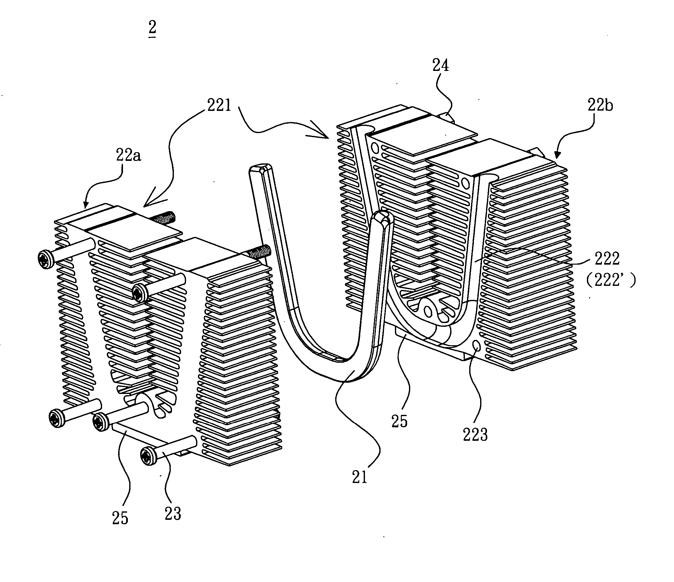
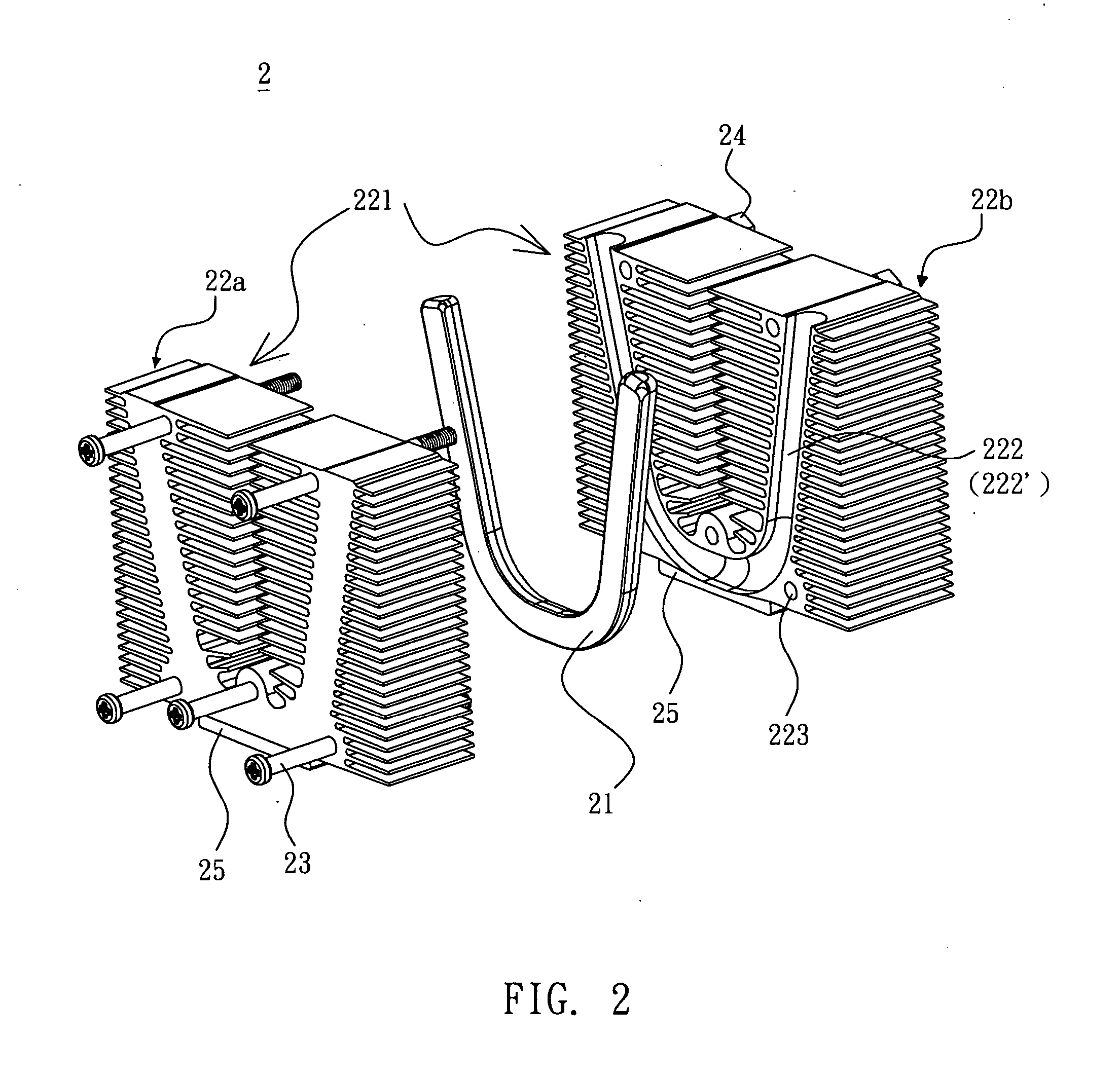
[0024]FIG. 2 is an exploded view showing a composite heat dissipating apparatus according to a preferred embodiment of the invention. FIG. 3 is an assembled view showing the composite heat dissipating apparatus of FIG. 2. Referring toFIGS. 2 and 3, a composite heat dissipating apparatus 2 includes a heat pipe 21 and two heat sinks 22a and 22b. The heat pipe 21 may contact a heat source (not shown) through a base 25, or directly contact the heat source so as to transfer the heat generated by the heat source to the heat sinks 22a and 22b directly and then the heat sinks 22a and 22b dissipate the heat out to the exterior. Herein, the heat source may be an electrical element, such as a CPU (Central Processing Unit), transistor, server, advanced graphics card, hard disk, power supply, ve...


PUM


Abstract

A composite heat dissipating apparatus includes a heat pipe and at least two heat sinks. The heat sinks are connected to each other. A space for accommodating the heat pipe therein is formed at a connection between the heat sinks. Each of the heat sinks is integrally formed as a single piece.

Description

[0001] This Non-provisional application claims priority under U.S.C.§ 119(a) on Patent Application No(s). 094128837, filed in Taiwan, Republic of China on Aug. 24, 2005, the entire contents of which are hereby incorporated by reference. BACKGROUND OF THE INVENTION [0002] 1. Field of Invention [0003] The invention relates to a heat dissipating apparatus, and in particular to a composite heat dissipating apparatus. [0004] 2. Related Art [0005] With the progress of the technology, the number of transistors in per unit area of the electrical element is getting larger and larger, and the heat generated as the transistors work is increased. On the other hand, the working frequency of the electrical element is getting higher and higher, so that the heat generated by the switch loss due to the on / off switching operations of the transistor mainly increases the total heat of the electrical element. If the heat is not dissipated properly, the operation speed of the chip is reduced, or even the...

Claims


Application Information

Patent Timeline
IPC IPC(8): H05K7/20
CPCF28D15/0266H01L23/427H01L23/467F28F2215/00H01L2924/0002F28F2215/10H01L2924/00F28D15/0275
Inventor LEE, CHENG-CHIHCHEN, TSUNG-LINLEE, WEN-TSAOCHEN, CHIN-MING
Owner DELTA ELECTRONICS INC
Why Eureka
Try Eureka