Optical receiving apparatus and method for controlling the optical receiving apparatus

Inactive Publication Date: 2007-03-01
FUJITSU LTD
View PDF8 Cites 45 Cited by
  • Summary
  • Abstract
  • Description
  • Claims
  • Application Information

AI Technical Summary

Benefits of technology

[0049] Accordingly, the present invention can provide an advantage that the dispersion compensation controlling unit can set, efficiently and optimally, the variable dispersion compensation unit in the optical receiving apparatus at the time of the initial setting (at the time of a start of the system operation, protection and

Problems solved by technology

For this, there is a problem that a long time is required to search optimum control amounts for both the delay interferometer and the variable dispersion compensator to obtain good quality of the received signal, which is harm to quickly stabilize the control amounts in the delay interferometer and the variable dispersion compensa

Method used


Image

  • Optical receiving apparatus and method for controlling the optical receiving apparatus
  • Optical receiving apparatus and method for controlling the optical receiving apparatus
  • Optical receiving apparatus and method for controlling the optical receiving apparatus

Examples


first embodiment

[A] Description of First Embodiment

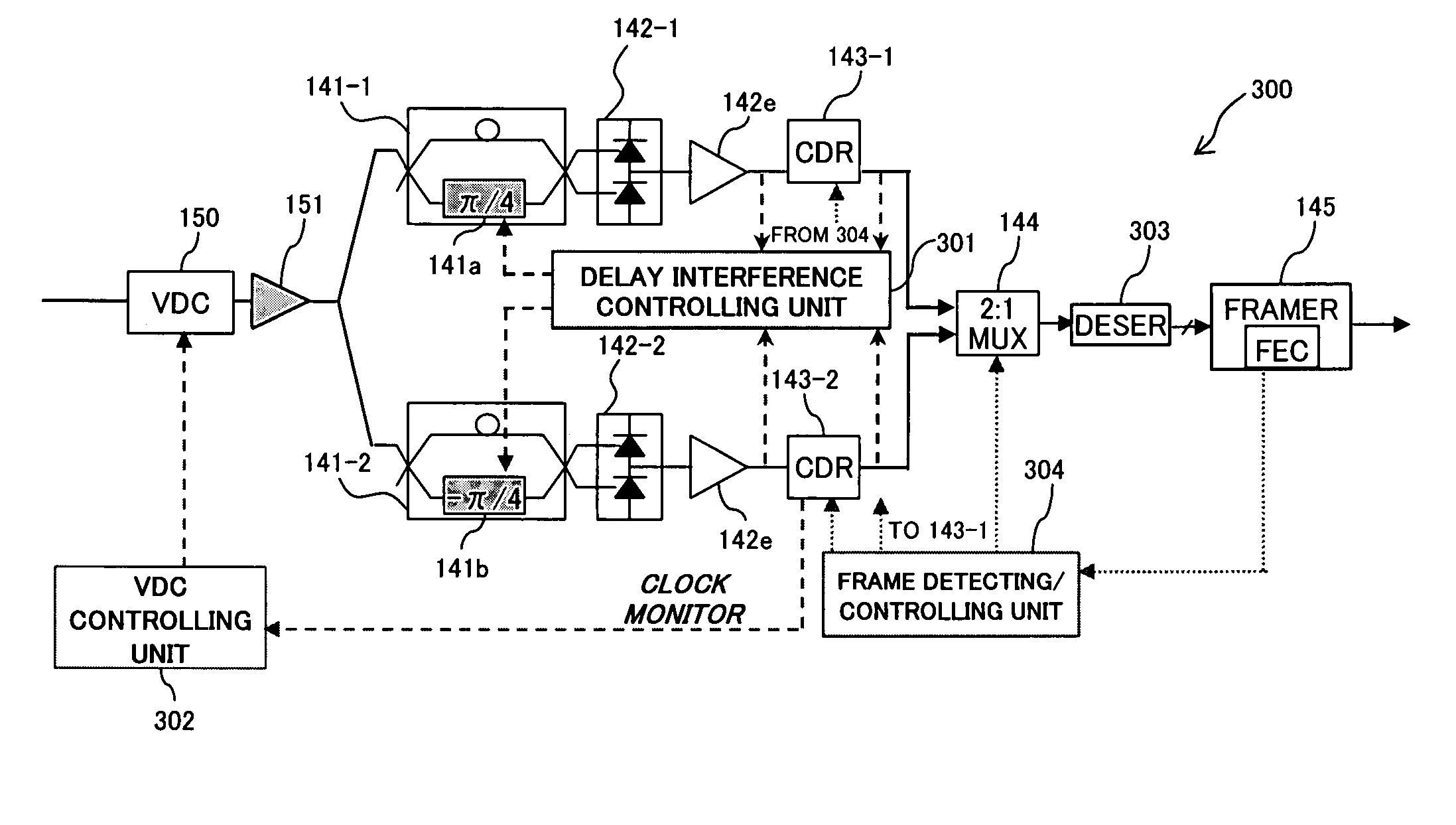
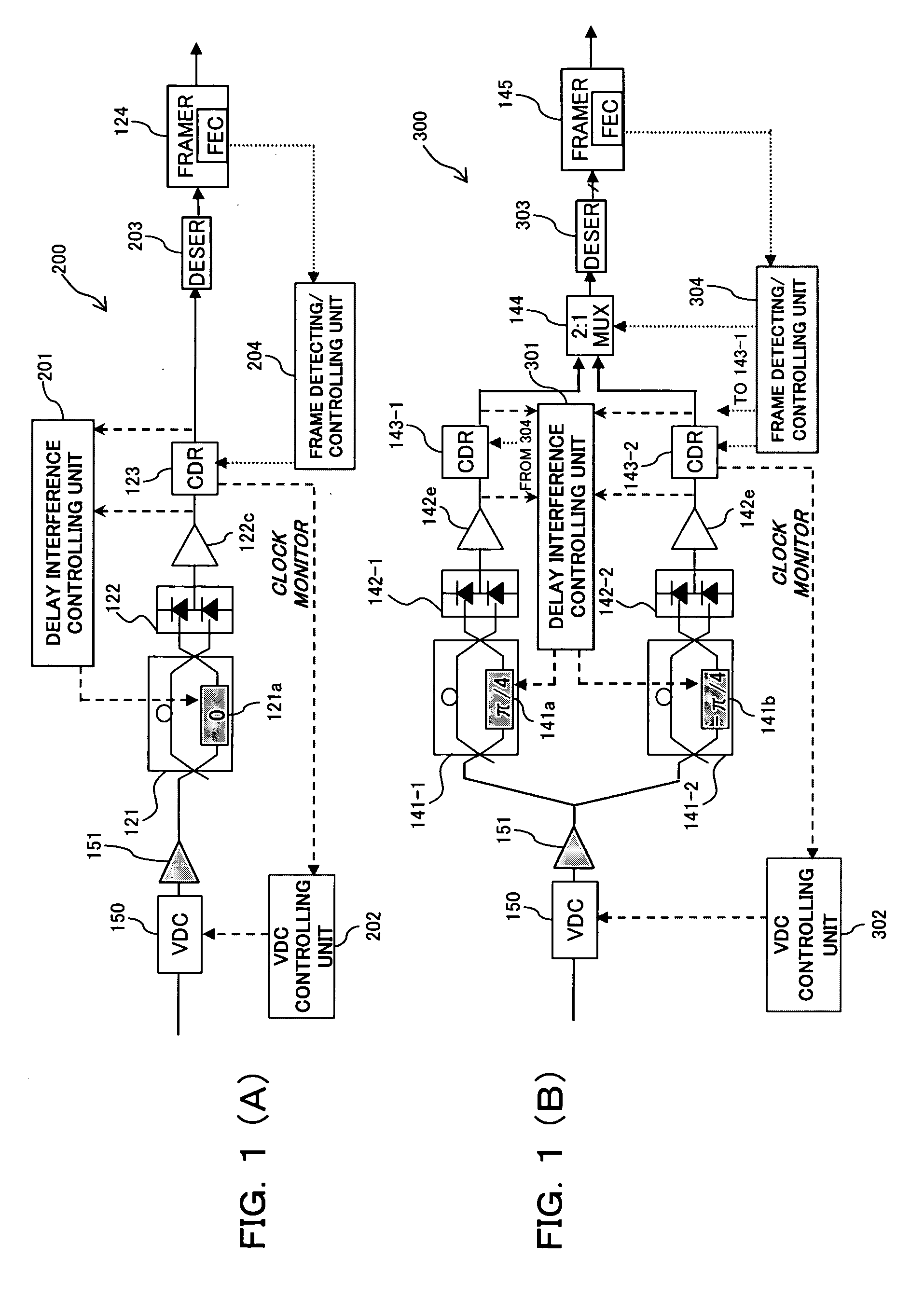
[0068] FIGS. 1(A) and 1(B) are diagrams showing optical receiving apparatuses 200 and 300 according to a first embodiment of this invention. The optical receiving apparatus 200 shown in FIG. 1(A) adopts (CS)RZ-DPSK modulation / demodulation system, which is differential binary phase modulation. The optical receiving apparatus 200 is an improvement of the above-mentioned optical receiving apparatus 120 shown in FIG. 30. The optical receiving apparatus 300 shown in FIG. 1(B) adopts (CS)RZ-DQPSK modulation / demodulation system, which is differential quaternary phase modulation. The optical receiving apparatus 300 is an improvement of the above-mentioned optical receiving apparatus 140 shown in FIG. 31.

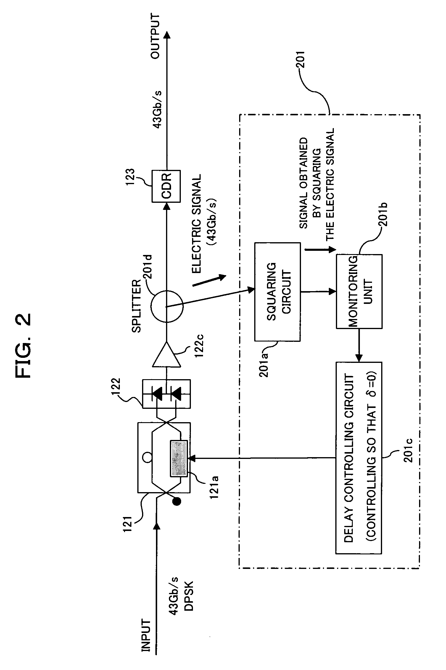
[0069] Like the delay interferometer 121 of the optical receiving apparatus 120 shown in FIG. 30, a delay interferometer 121 of the optical receiving apparatus 200 shown in FIG. 1(A) is a delay interference unit for performing a delay interference process ...

second embodiment

[B] Description of Second Embodiment

[0125] FIGS. 26(A) and 26(B) are block diagrams showing optical receiving apparatuses 210 and 310 according to a second embodiment of this invention. The optical receiving apparatus 210 shown in FIG. 26(A) adopts (CS)RZ-DPSK modulation / demodulation system, which is differential binary phase modulation. The optical receiving apparatus 210 is characterized by a control sequence for setting the dispersion compensation amount in a VDC 150, and a control sequence for setting the phase control amount in a delay interferometer 121.

[0126] The optical receiving apparatus 310 shown in FIG. 26(B) adopts (CS)RZ-DQPSK modulation / demodulation system, which is differential quaternary phase modulation. The optical receiving apparatus 310 is characterized by a control sequence for setting the dispersion compensation amount in a VDC 150 and a control sequence for setting the phase control amount in delay interferometers 141-1 and 141-2. Incidentally, like referenc...


PUM


Abstract

An optical receiving apparatus sets, efficiently and optimally, a delay interferometer and a variable wavelength dispersion compensator in the apparatus. The apparatus has a variable dispersion compensation unit performing variably dispersion compensation on a received optical signal, a delay interference unit performing a delay interference process on the optical signal from the variable dispersion compensation unit, a photoelectric conversion detecting unit performing photoelectric conversion detection on the optical signal from the delay interference unit and outputting an electric signal demodulated from the differential M-ary phase modulated optical signal, a clock signal extracting unit extracting a clock signal from the demodulated electric signal fed from the photoelectric conversion detecting unit, and a dispersion compensation controlling unit controlling a dispersion compensation amount in the variable dispersion compensation unit on the basis of the clock signal extracted by the clock signal extracting unit.

Description

BACKGROUND OF THE INVENTION [0001] 1) Field of the Invention [0002] The present invention relates to an optical receiving apparatus and a method for controlling the optical receiving apparatus suitable for use in an optical transmission system, particularly, an optical transmission system adopting optical phase modulation and demodulation. [0003] 2) Background of the Invention [0004] In these years, there is a growing demand for introduction of a 40 Gbit / s optical transmission system in the next generation. In addition, a transmission distance and frequency utilization efficiency equivalent to those of the 10 Gbit / s system are also demanded. RZ-DPSK (Differential Phase Shift Keying) or CSRZ-DPSK, which has excellent optical signal-to-noise ratio (OSNR) tolerance and nonlinearity tolerance as compared with NRZ (Non Return to Zero) employed in known systems of not larger than 10 Gb / s, is being vitally researched and developed as a means meeting the above demands. Besides the above mod...

Claims


Application Information

Patent Timeline
IPC IPC(8): H04B10/12H04B10/2507H04B10/07H04B10/2513H04B10/516H04B10/548H04B10/588H04B10/61
CPCH04B10/66
Inventor OOI, HIROKIMIURA, AKIRAHOSHIDA, TAKESHI
Owner FUJITSU LTD
Why Eureka
Try Eureka