

Wireless spacecraft operational and testing communications network
- Summary
- Abstract
- Description
- Claims
- Application Information
AI Technical Summary
Benefits of technology
Problems solved by technology
Method used
Image

Examples
Embodiment Construction
[0018] In the following description, reference is made to the accompanying drawings which form a part hereof, and which is shown, by way of illustration, several embodiments of the present invention. It is understood that other embodiments may be utilized and structural changes may be made without departing from the scope of the present invention.
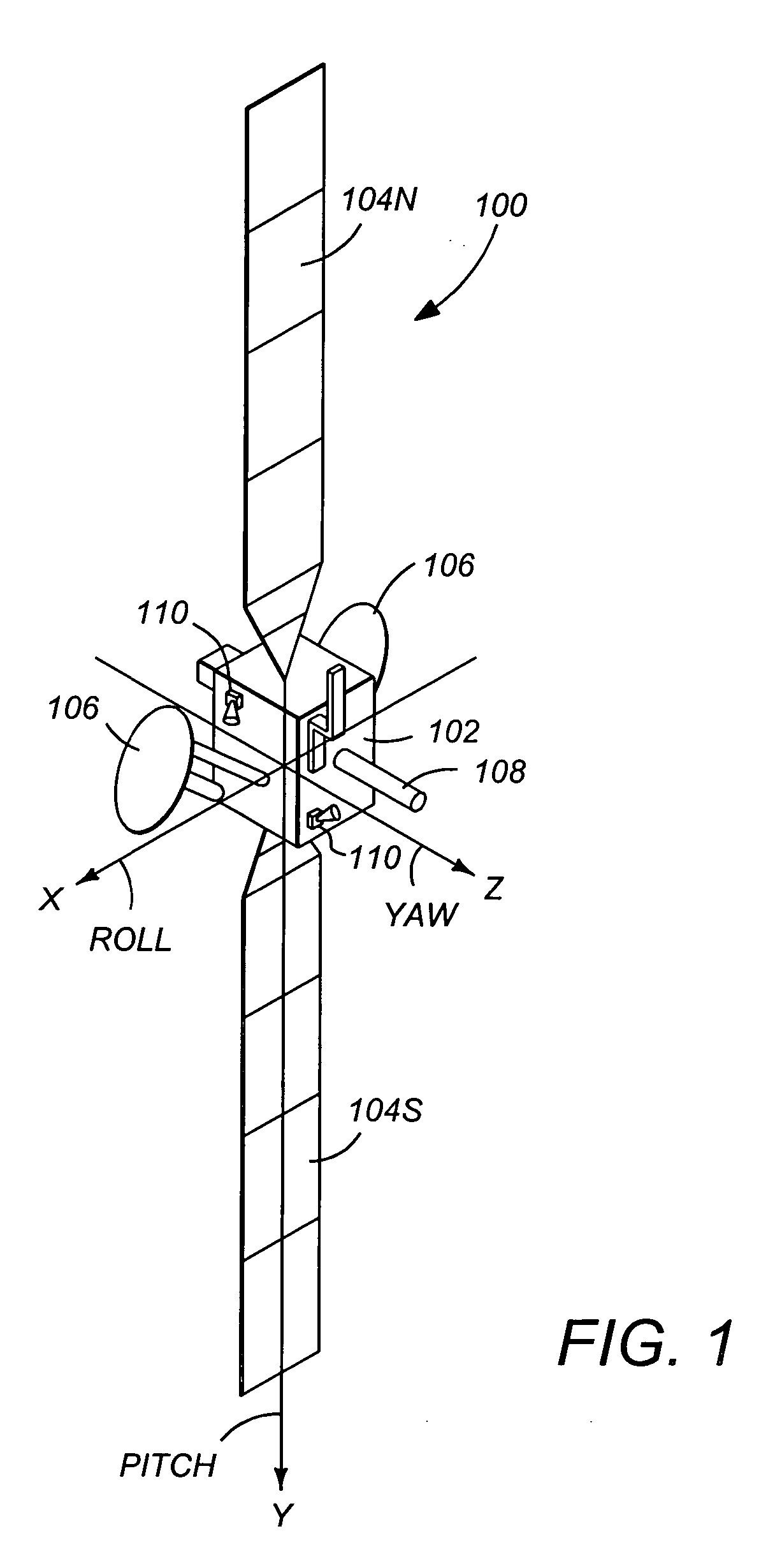
[0019]FIG. 1 is a diagram illustrating a three-axis stabilized satellite or spacecraft 100. The spacecraft 100 has a main body 102, a pair of solar panels 104, a pair of high gain narrow beam antennas 106, and a telemetry and command omnidirectional antenna 108 which is aimed at a control ground station. The spacecraft 100 may also include one or more sensors 110 to measure the attitude of the spacecraft 100. These sensors may include sun sensors, earth sensors, and star sensors. Since the solar panels are often referred to by the designations “North” and “South”, the solar panels in FIG. 1 are referred to by the numerals 104N and 104S for...
PUM
 Abstract
Description
Claims
Application Information