Apparatus and method for forming concrete panels

a technology of concrete panels and apparatus, applied in the direction of moulding surfaces, moulding fastening means, shaping building parts, etc., can solve the problems of inability to reuse, form damage, and cast surface damag

Inactive Publication Date: 2007-03-08
SPEEDLINE PANEL FORMERS
View PDF3 Cites 14 Cited by
  • Summary
  • Abstract
  • Description
  • Claims
  • Application Information

AI Technical Summary

Problems solved by technology

Placing and fixing the forms for the panels, and subsequently removing those forms presents a number of problems.
The forms are often damaged when the nails or screws are removed so that they cannot be reused.
The casting surface is often damaged as well.
However, these strips can often be displaced when the concrete is poured leading to irregular panels being formed.
Practically, this means that the panels are limited in thickness to standard plywood widths.
This means that each panel requires a separate form and takes up considerable space on the casting floor.
It is not possible to stick brackets on either side of the form in this scheme as they would interfere with the shape of the concrete panels.
However, existing forms cannot be anchored strongly enough to the casting floor to withstand the pressure from the concrete without external brackets.
There are a number of problems with the system of U.S. Pat. No. 6,322,045.
Firstly, concrete can enter the gap between the plywood and the extruded form member.
This will make it almost impossible to remove the plywood from the form member without signi

Method used


Image

  • Apparatus and method for forming concrete panels
  • Apparatus and method for forming concrete panels
  • Apparatus and method for forming concrete panels

Examples


Embodiment Construction

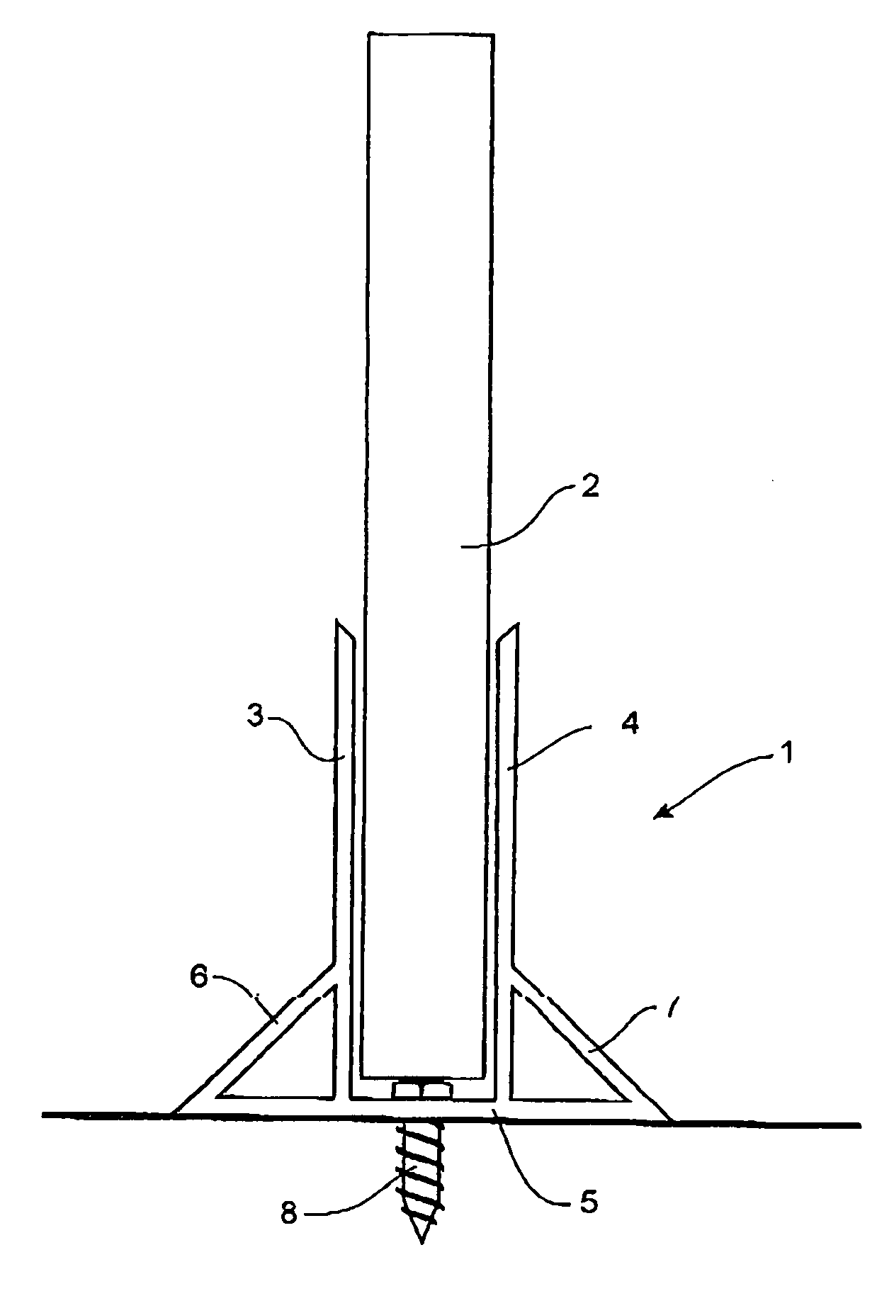
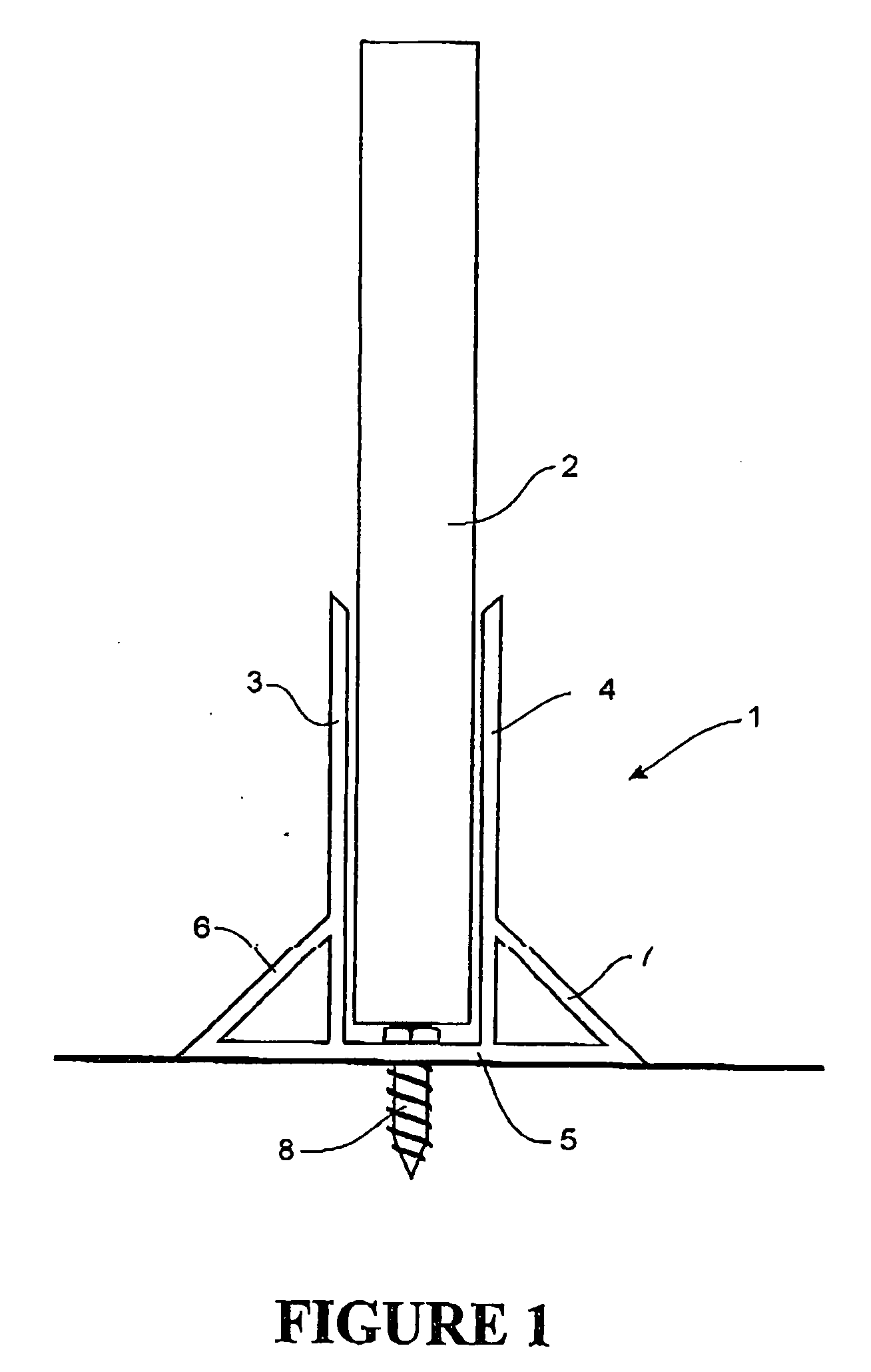
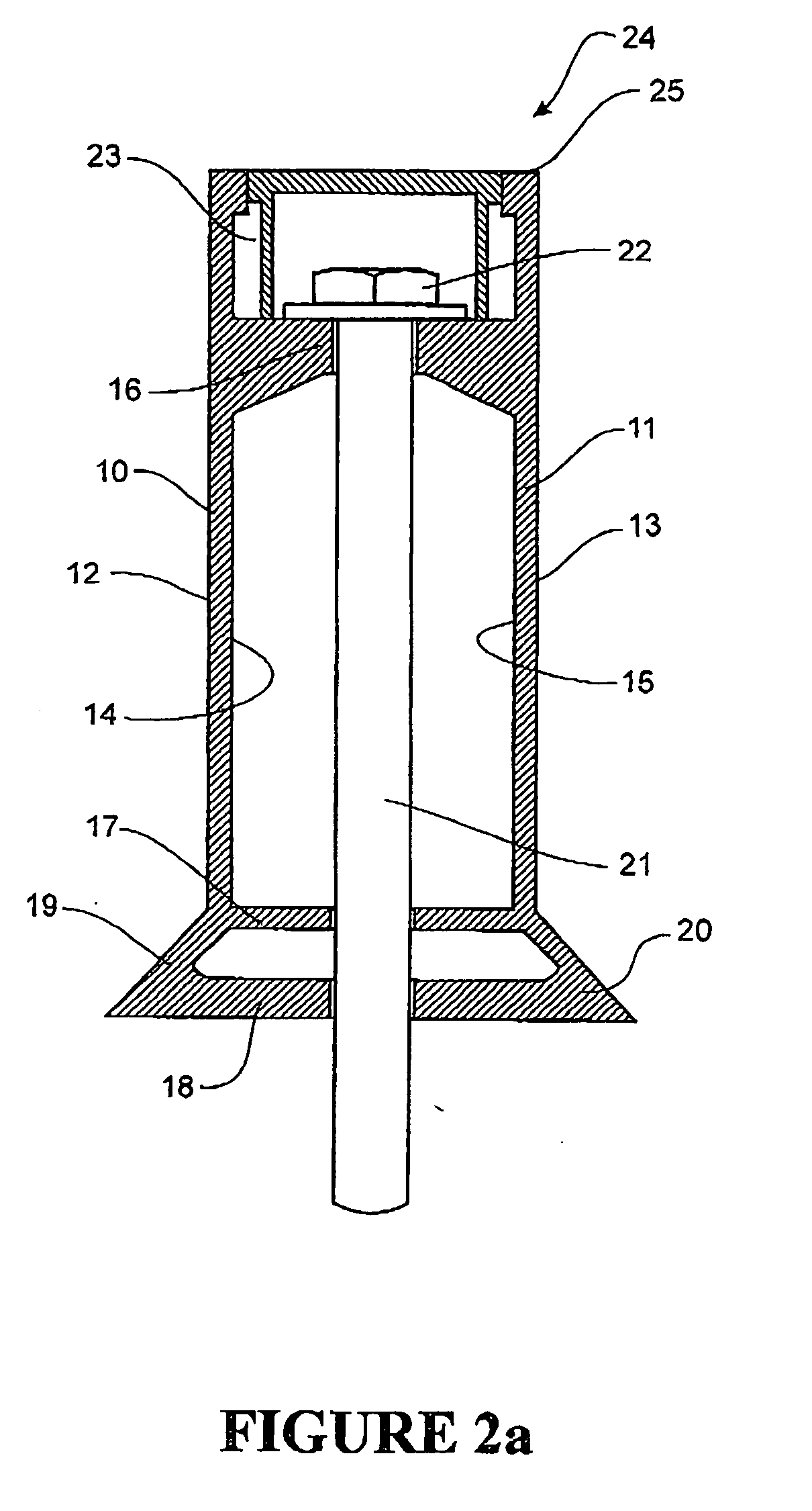
[0055]FIG. 2a is a cross-section of a form member 24 in accordance with the present invention. The form member comprises a pair of upright walls 10, 11 which are connected at their inner surfaces 14, 15 by a plurality of ribs 16, 17 and a base member 18. The form member includes a pair of chamfered surfaces 19, 20 extending between the upright walls 10, 11 and the base member 18. In this example, the external surfaces of the upright walls 12, 13 are parallel to one another and substantially perpendicular to the base member. However, it should be appreciated that the external surfaces can have any desired profile. It should also be appreciated that the chamfered surfaces 19, 20 are optional as is base member 18. The form member 24 also includes a flat top surface 25. This flat top surface is also optional.

[0056] The form member is of substantially uniform cross-section, except for a series of apertures for receiving fasteners positioned along its length. This is clearly seen in FIG....


PUM


Abstract

The invention provides a form member for use in forming concrete panels comprising a pair of upright walls connected by a plurality of ribs. Each of the ribs includes an aperture for allowing a fastener through. The fastener passes through each of the ribs into a casting floor to fix the form member to the floor. A plurality of form members can be arranged to define enclosures, concrete is then poured into the enclosures to the level of the upright walls, smoothed and allowed to cure to form concrete panels. The form members of the present invention allow a number of panels to be formed at the same time, with some form members common to more than one concrete panel. The invention provides easy of use and savings in space, time and labour.

Description

BACKGROUND OF THE INVENTION [0001] 1. Field of the Invention [0002] The present invention relates to an apparatus and method for forming concrete panels. In particular, the invention relates to forming tilt-up concrete panels which are poured on a flat surface and subsequently tilted up to form walls for buildings. [0003] 2. Background of the Invention [0004] Tilt-up construction is a method of forming concrete buildings. It provides a low cost and high speed way to construct buildings which are low maintenance and have good durability. [0005] Typically, in a tilt-up concrete construction, panels are formed as near to their final position in the building as possible. The most convenient casting base is often the concrete floor of the building. Wood or steel edge forms are prepared and positioned on a casting base. The base is sprayed with a release agent that prevents wet concrete sticking to the base. Reinforcing steel and any desired door and window frames, electric conduits and o...

Claims


Application Information

Patent Timeline
IPC IPC(8): E04G9/00
CPCB28B7/0017B28B7/0032E04G21/16E04G13/00E04G17/001B28B7/0085E04G17/004
Inventor KNOWLES, STEPHEN CRAIG
Owner SPEEDLINE PANEL FORMERS
Why Eureka
Try Eureka