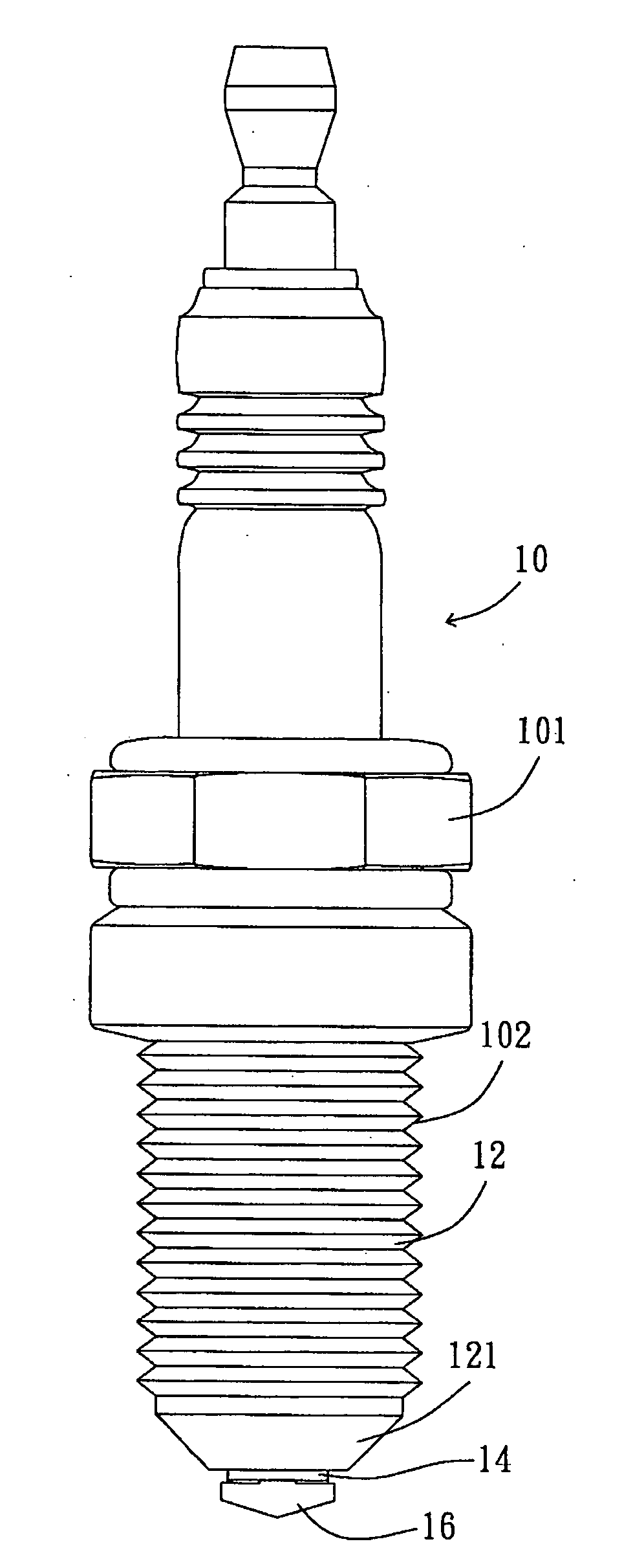
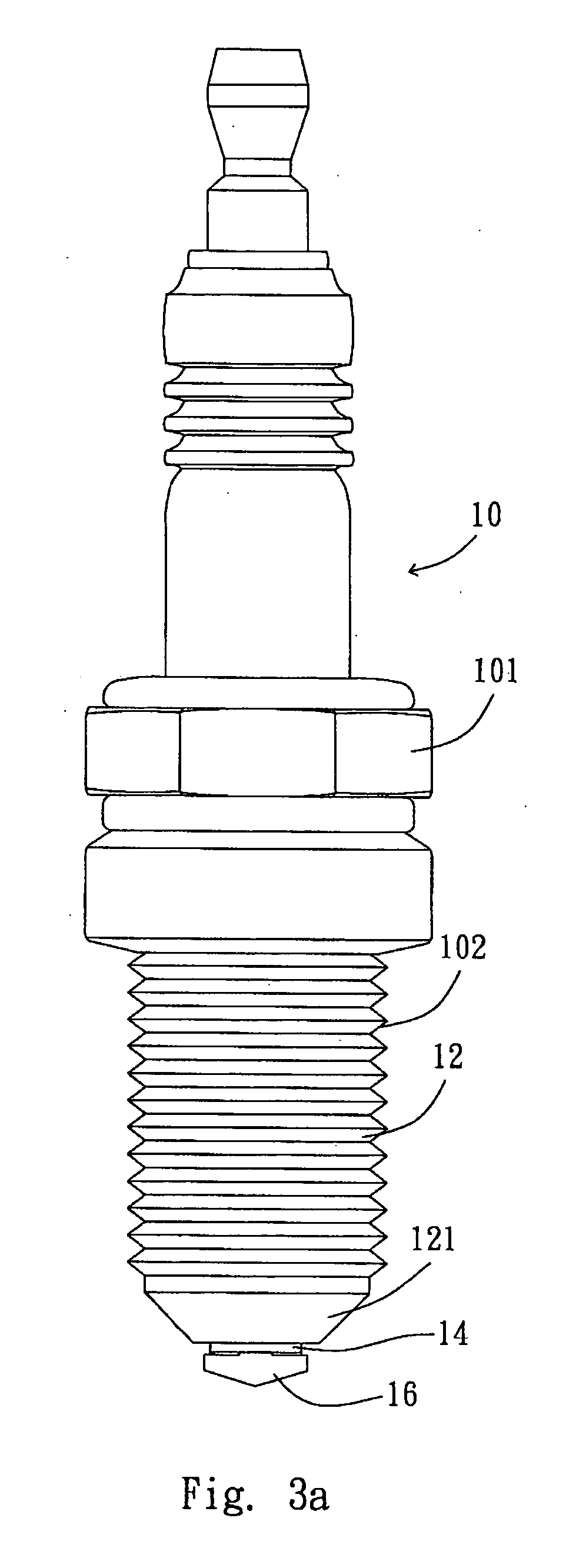
Spark plug

a spark plug and plug-in technology, applied in spark plugs, basic electric elements, electric devices, etc., can solve the problems of slow ignition, incomplete combustion, and substantially reduced ignition efficiency of curviform sparks, so as to increase ignition efficiency and optimize fuel efficiency

Inactive Publication Date: 2007-03-08
VITAL TECH APPL COMPANY
View PDF12 Cites 12 Cited by
  • Summary
  • Abstract
  • Description
  • Claims
  • Application Information

AI Technical Summary

Benefits of technology

[0011] Another objective of the present invention is to provide at least one rotatable auxiliary electrode for not only igniting spark discharges more efficiently, but also extending the life span of a spark plug by slowing the oxidization rate.
[0013] Another objective of the present invention is to increase the ignition efficiency and optimize the fuel efficiency.

Problems solved by technology

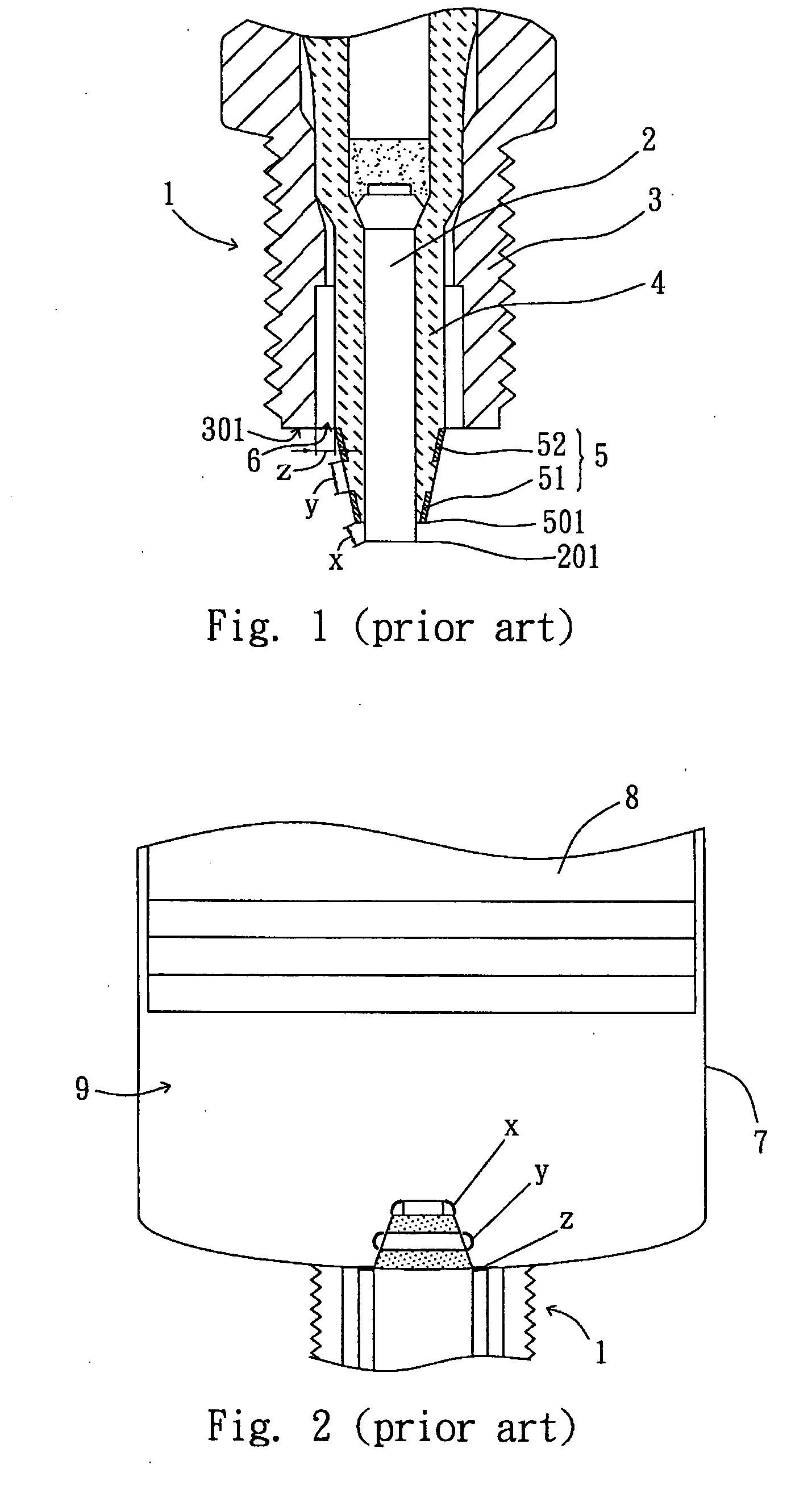
However, a curviform spark discharge substantially reduces the ignition efficiency.
It results in slow ignition and incomplete combustion.
In other words, some fuel is exhausted before complete combustion; it causes not only a waste, but also air pollution.
Moreover, fuel-air and greasy filth easily get into recess 6 and effect the ignition of spark discharge z. It causes a circuit-short of the spark plug and incomplete combustion.

Method used


Image

  • Spark plug
  • Spark plug
  • Spark plug

Examples


second embodiment

[0033] Please refer to FIG. 5 and FIG. 6, which show the present invention provided to separately generate three circular sparks. The spark plug 20 comprises a housing 20, a ceramics insulator 24 and two auxiliary ring-shaped electrodes 23. Wherein the housing 20 has an inner cavity 203 disposed within it and threads 102 on the lower part of the housing 20 for assembling into the engine block. The size of the ceramics insulator 24 varies with different pitch gauges of the threads 202. The ceramics insulator 24 encloses a central electrode 26. Two depressions 241 are formed on the protruding end of the ceramics insulator 24. The ceramics insulator 24 is disposed in the inner cavity 204, and a gap 204 is formed between the housing 22 and the ceramics insulator 24. The central electrode 26 has a body 261 and a head 262. The head 262 radially extends from one end of the body 261, and the outer surface of the head 262 is preferably formed with a taper. The central electrode 26 of this em...

fourth embodiment

[0038] the present invention is illustrated hereinafter accompanying with FIG. 13. The spark plug 40 comprises an electrically and thermally conductive housing 42, a ceramics insulator 44 and a single auxiliary ring-shaped electrode 43. The conductive housing 42 has an inner cavity 403 disposed within it and threads 402 on its lower part for assembling into the engine block. The size of the ceramics insulator 44 varies with different pitch gauges provided by threads 402. The central electrode 46 disposed inside the inner cavity 403 of the ceramics insulator 44. The depression 441 is formed on the protruding end of the ceramics insulator 44 and a gap 204 is formed between the housing 42 and the ceramics insulator 44. Auxiliary ring-shaped electrode 43 is rotatively disposed in depression 441. Wherein the auxiliary ring-shaped electrode 43 is exposed from the housing 42.

[0039] In this embodiment, the central electrode 46 has a stick shape. Auxiliary ring-shaped electrode 43 is rotativ...


PUM


Abstract

A spark plug provided to ignite fire and generate power for an engine, comprises an outer layer with an inner cavity and a ceramics insulator enclosing a central electrode inside the inner cavity. A gap is located between the ceramics insulator and the housing. The central electrode has a body and a head. One end of the body radically extends and forms a tip. The present invention improves ignition and fuel efficiency, thereby reducing air pollution.

Description

[0001] This application claims priority based on a Taiwanese patent application No. 094130040 filed on Sep. 2, 2005. BACKGROUND OF THE INVENTION [0002] 1. Field of the Invention [0003] The present invention relates to a spark plug. Specially, the present invention relates to a spark plug that improves the efficiency in motors. [0004] 2. Description of the Relative Art [0005]FIG. 1 shows a prior art spark plug 1. A ceramics insulator 4 encloses a central electrode 2 to prevent a high-voltage short circuit or electric leakage. Between the ceramics insulator 4 and housing 3 there are asbestos, ceramic powder filing and copper ring, wherein the ceramics insulator 4 is inserted in the housing 3 to form a gas-proof body for preventing engine's pressure leakage. Two ring-shaped auxiliary electrodes 51 and 52 are disposed on the ceramics insulator 4 wherein the outer peripheral rim 501 of the first upper ring-shaped auxiliary electrode 51 is lower than the end of the central electrode 201. ...

Claims


Application Information

Patent Timeline
Patent Type & Authority Applications(United States)
IPC IPC(8): H01T13/20
CPCH01T13/20
Inventor LIAO, CHEN CHUN
Owner VITAL TECH APPL COMPANY
Why Eureka
Try Eureka