
Object detection method and apparatus

a detection method and object technology, applied in the field of object detection methods and apparatuses, can solve the problems of suicide bomber, more dangerous and devastating, new threat has evolved,

Inactive Publication Date: 2007-03-08
MACALEESE
View PDF61 Cites 43 Cited by
  • Summary
  • Abstract
  • Description
  • Claims
  • Application Information

AI Technical Summary

Benefits of technology

[0017] An advantage of the present invention is that the power levels radiated by the present invention are preferably much lower than conventional radar systems or those generated by x-ray or other imaging systems that are currently employed to detect objects at the entry of an airport or a courtroom. For the present invention the average power density at the target is orders of magnitude below the safety limit for non-ionizing radiation.

Problems solved by technology

Furthermore, in recent years, a new threat has evolved; that is the suicide bomber.
These are more dangerous and more devastating and because of the nature of their weapon, it is imperative that they be detected at a long distance.
Many previous efforts to reduce the threat posed by the criminal use of firearms have met with limited success.
In the past two decades, very expensive x-ray equipment has been installed in major airports.
This type of equipment requires a fixed installation, occupies a very large space, is close-range and may cost hundreds of thousands or even millions of dollars.
None of the complex concealed weapon detectors that are currently available in the commercial market are compact, lightweight, portable, easy to use, long-range and highly reliable.

Method used


Image

  • Object detection method and apparatus
  • Object detection method and apparatus
  • Object detection method and apparatus

Examples


example 1

[0121] Targets which were tested for detection include a variety of weapons, including a .22 caliber pistol, a Glock 9 mm semiautomatic pistol, an Uzi assault rifle, and a variety of terrorist style bombs including those comprising nails as shrapnel, slingshot balls as shrapnel and explosive simulation packets without shrapnel. Table 2 displays sample test data regarding the detection of a variety of weapons in accordance with the present invention using the 9.5 to 10.7 GHz frequency band and illuminated with horizontal polarization. Data were taken for front views only. This data was taken using 12 different people whose size and weight spanned from about 100 pounds to 220 pounds and heights from about 5′0″ to 6′2″. As shown, the system was correct for 115 out of 116 safe cases thereby yielding only one false positive and zero false negatives out of 283 weapon cases. (NA means not applicable.)

TABLE 2NumberCor-%FalseFalseCaseof TestsrectCorrectNegativesPositivesCautions.22 Pistol6...


PUM


Abstract

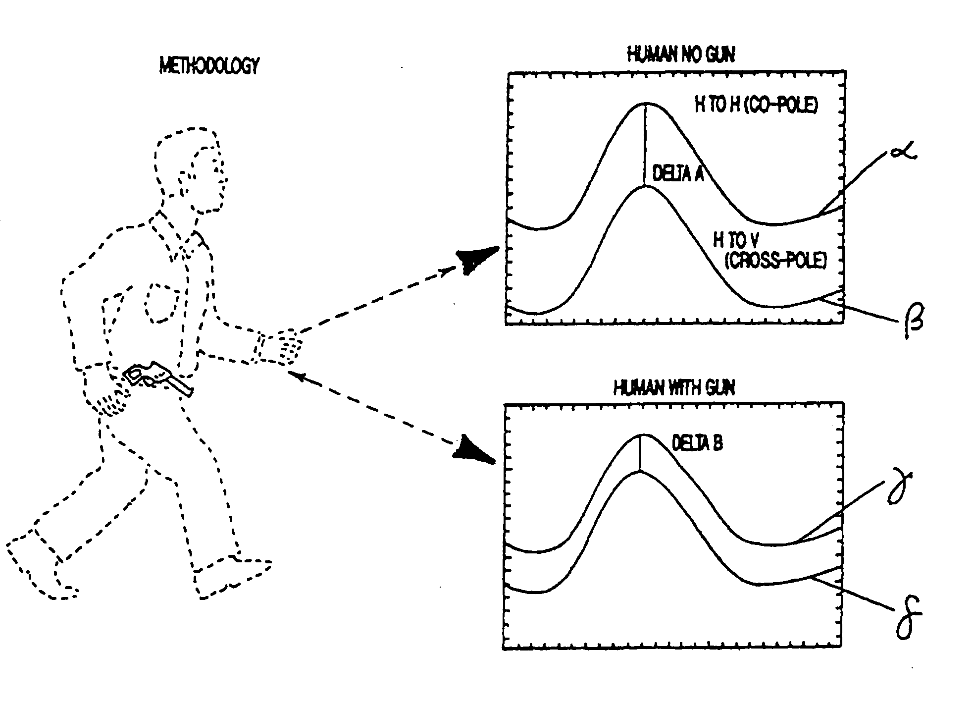
Method and apparatus for detecting objects. In one embodiment, a person entering a secured zone is illuminated with low-power polarized radio waves. Differently polarized waves which are reflected back from the person are collected. Concealed weapons are detected by measuring various parameters of the reflected signals and then calculating various selected differences between them. These differences create patterns when plotted as a function of time. Preferably a trained neural network pattern recognition program is then used to evaluate these patterns and autonomously render a decision on the presence of a weapon. An interrupted continuous wave system may be employed. Multiple units may be used to detect various azimuthal angles and to improve accuracy.

Description

CROSS-REFERENCE TO RELATED APPLICATIONS [0001] This application claims the benefit of the filing of U.S. Provisional Patent Application Ser. No. 60 / 680,627, entitled “Object Detection Method and Apparatus”, filed on May 12, 2005. This application is also a continuation-in-part application of U.S. patent application Ser. No. 10 / 997,845, entitled “Object Detection Method and Apparatus”, filed on Nov. 24, 2004, which claims the benefit of the filing of U.S. Provisional Patent Application Ser. No. 60 / 525,637, entitled “Object Detection Method and Apparatus Employing Polarized Radiation and Artificial Intelligence Processing”, filed on Nov. 25, 2003, and which is also a continuation-in-part application of U.S. patent application Ser. No. 10 / 340,016, entitled “Signal Processing for Object Detection System”, filed on Jan. 9, 2003, which is a continuation-in-part of U.S. patent application Ser. No. 10 / 060,641, entitled “Signal Processing for Object Detection System”, filed on Jan. 29, 2002,...

Claims


Application Information

Patent Timeline
IPC IPC(8): G01S13/04G01S7/40
CPCG01S7/024G01S13/887G01S13/04G01S7/411
Inventor HAUSNER, JERRYWEST, JONATHAN M.
Owner MACALEESE
Learn More