Antenna positioner for portable satellite terminal

a satellite terminal and portable technology, applied in the direction of antennas, transmission, electrical equipment, etc., can solve the problems of angular sensors for azimuth, relatively large (deep) structures, and pressure on the motor axle, and achieve the effect of free of backlash or slippag

Inactive Publication Date: 2007-03-08
NORSAT INTERNATIONAL
View PDF0 Cites 26 Cited by
  • Summary
  • Abstract
  • Description
  • Claims
  • Application Information

AI Technical Summary

Benefits of technology

[0022] An azimuth angle sensor using a circular potentiometer with large circumference thus providing better accuracy, resolution and freedom from slippage or backlash compared to prior art.
[0024] A polarization adjustment mechanism incorporating a polarization angle sensor using a circular potentiometer. As in the azimuth part of the positioner, better accuracy, resolution and freedom from slippage or backlash is obtained compared to prior art
[0025] This invention includes an azimuth drive and azimuth angle sensor for use in a motorized antenna positioner for a small portable satellite terminal. The drive mechanism is sufficiently robust to reliably turn a 1 m antenna while having a very low profile. That enables the azimuth drive to be incorporated in the box housing the terminal's electronics without significantly affecting its dimensions. The novel angular sensor has improved accuracy and resolution over prior art.
[0029] The invention further includes a polarization adjustment drive and angle sensor for use in a motorized antenna positioner for a small portable satellite terminal. The novel aspect of the polarization adjustment assembly is its angular sensor that, similar to the one in the azimuth unit, has improved accuracy and resolution over prior art.
[0032] The current invention provides a solution that is free of backlash or slippage.

Problems solved by technology

In addition to the purely mechanical aspects, there is also the issue of angular sensors for azimuth, elevation and polarization.
Further, the disadvantage of the above solutions is that the multi-turn devices used result in relatively big (deep) structures compared to the simple one-turn pulley and drum combination.
One of the problems in motorized elevation adjustment structures is the pressure exerted on the motor axle due to the weight of the antenna, pushing downwards, or pulling upwards, depending on the elevation angle.
This can have a negative effect on the performance and reliability of the motor.
The patents mentioned above, concerned primarily with mechanics, do not address this.
The disadvantage of the above solutions is the relatively low accuracy and resolution of regular potentiometers and the potential slippage or backlash depending on the method of mechanical coupling to the potentiometers.

Method used


Image

  • Antenna positioner for portable satellite terminal
  • Antenna positioner for portable satellite terminal
  • Antenna positioner for portable satellite terminal

Examples


Embodiment Construction

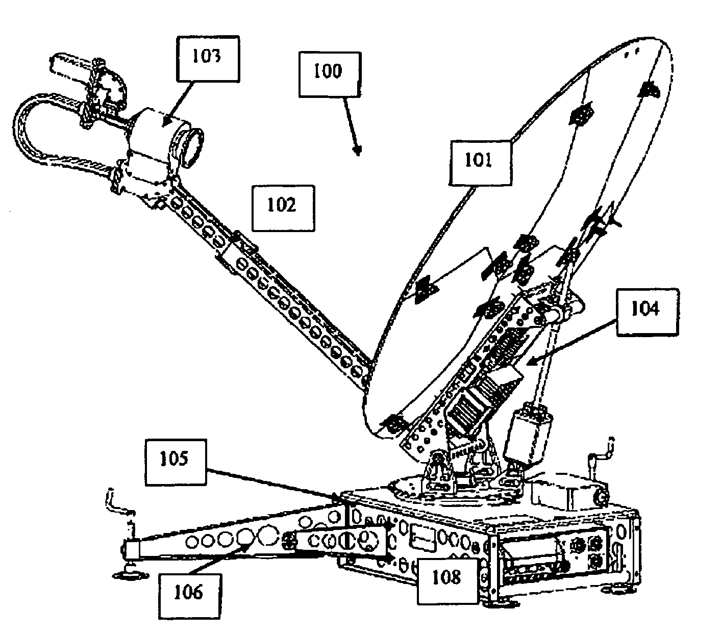
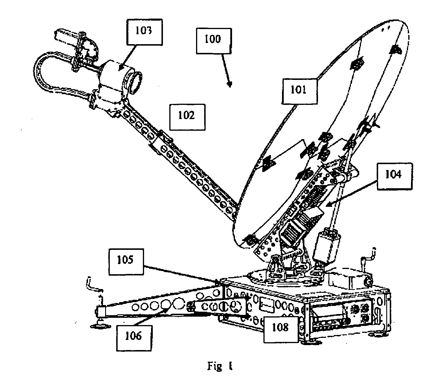
[0052] The antenna positioner and sensing mechanisms of this invention are preferably part of a portable communication unit capable of transmitting / receiving high-speed data and broadcast quality video via satellite. However, they may be used in a wide variety of settings and applications. To achieve good performance while preventing undue interference to or from other systems, a 1-meter parabolic antenna is preferably employed, together with a powerful RF amplifier. For ease of setup, the unit preferably contains all the necessary hardware and software for automatic acquisition of the desired satellite.

[0053] As shown in FIG. 1, the communication unit 100 is a portable satellite terminal consisting of a 1 m diameter parabolic segmented antenna 101 with a boom assembly 102 with a feed horn and receiver assembly 103 mounted on the end. The boom assembly 102 breaks into two parts for disassembly and transport. On the lower back part of the antenna 101, the RF transmit (Tx) electronic...


PUM


Abstract

A motorized antenna positioning mechanism in a portable microwave communication unit for use as a ground station in a satellite communication system. The antenna positioner has compact and low profile azimuth wire drive mechanics, azimuth and polarization angle sensors that are not affected by slippage and backlash, and an elevation drive mechanism which neutralizes the pressure on the motor axis due to the weight of the parabolic antenna.

Description

RELATED APPLICATIONS [0001] The present application claims the benefit of U.S. patent application Ser. No. 11 / 220,549, filed Sep. 8, 2005.FIELD OF THE INVENTION [0002] The present invention relates to antenna positioning systems in certain types of portable terminals for satellite communications where automatic, rather than manual, alignment to the desired satellite is preferred. BACKGROUND OF THE INVENTION [0003] Typically, such terminals are found in Satellite News Gathering (SNG) and in some military communication systems. Because of the performance required, terminals of this kind are not intrinsically very small, as parabolic antennas around 1m in diameter are needed. This, in conjunction with the automatic acquisition feature, results in certain mechanical and electrical requirements on the positioner that this invention solves in a novel way. [0004] In antenna positioners, or positioning systems, the mechanisms for adjusting the azimuth, elevation and polarization angles are ...

Claims


Application Information

Patent Timeline
Patent Type & Authority Applications(United States)
IPC IPC(8): H01Q3/00
CPCH01Q3/08H04B1/3888H04B1/086H01Q19/13
Inventor DWORNIK, GLEN ALLANRUSSELL, LEONARD ALBERTTRESSEL, WAYNESCHEFTER, MICHAEL JOHNYANG, JOSEPHTRAJKOVIC, SASA TRAJKOBEZUIDENHOUT, PETRUS
Owner NORSAT INTERNATIONAL
Why Eureka
Try Eureka