Pixel optimization for color

a color image sensor and optimization technology, applied in the field of image sensors, can solve the problems of increasing requiring increased space, and having no effect on the difference in s/n, so as to increase the cost of the imager and increase the space

Inactive Publication Date: 2007-03-08
MICRON TECH INC
View PDF13 Cites 179 Cited by
  • Summary
  • Abstract
  • Description
  • Claims
  • Application Information

AI Technical Summary

Benefits of technology

[0004] Separate gain elements for corresponding spectral band channels can be used to equalize the output signals of the different color sensors to compensate for differences in responsivity. However, the gain elements increase the cost of the imager, require increased space, and have no effect on the differences in S / N for the different color pixels.

Problems solved by technology

However, the gain elements increase the cost of the imager, require increased space, and have no effect on the differences in S / N for the different color pixels.

Method used


Image

  • Pixel optimization for color
  • Pixel optimization for color
  • Pixel optimization for color

Examples


Embodiment Construction

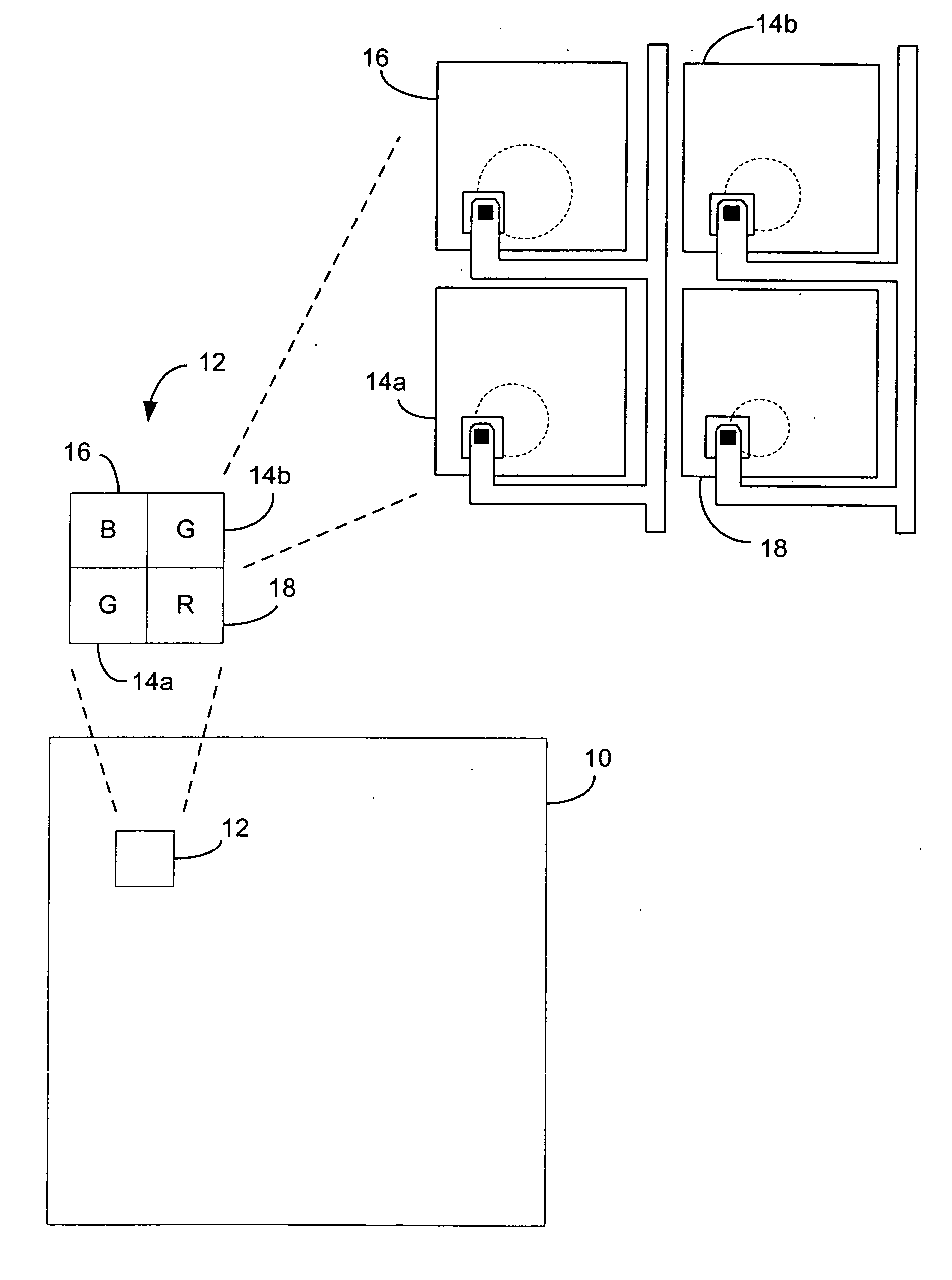
[0014] An embodiment of a color imaging system 10 in accordance with the teachings of the invention is shown in FIG. 1. The color imaging system 10 includes an array of macro pixels 12, each converting received light into an electrical output signal. Each macro pixel 12 is preferably comprised of two green pixels 14a and 14b, a red pixel 18, and a blue pixel 16 that are configured in a Bayer pattern. Although a Bayer pattern pixel configuration is preferable, other pixel configurations that include two or more different color pixels including non-primary colors may be used.

[0015] The output signal of each color pixel is described by the following equation:

Vnαphin*Tn*An*etan*Gn

where n=1, 2, 3 . . . is the spectral band (e.g., 3 bands in the case of RGB), phin is the flux per unit area of each pixel, Tn is the transmission of each spectral band filter, An is the collection area of each pixel, etan is the quantum efficiency of each pixel, and Gn is the conversion gain of each pixel...


PUM


Abstract

A macro pixel is provided. The macro pixel includes at least two color pixel elements. Each color pixel element includes a photoreceptor that in response to receiving light, generates an output signal that is indicative of the quantity of light photons of a color are received. Each of the color pixel elements are configured to receive a corresponding color. The photoreceptor of each color pixel element has a geometry and a responsivity to light that is a function of the geometry of the photoreceptor such that the responsivity of the output signal of the photoreceptor to the corresponding color is controllable by changing the geometry. The geometries of the photoreceptors are selected so that a predetermined relative sensitivity to each color is obtained

Description

CROSS-REFERENCE TO RELATED APPLICATIONS [0001] This application claims the benefit of the filing date of U.S. provisional application No. 60 / 223,396 filed Aug. 7, 2000, the content of which is herein incorporated by reference in its entirety.TECHNICAL FIELD [0002] The present invention relates generally to image sensors and in particular, to complementary metal oxide semiconductor (CMOS) color image sensors. BACKGROUND AND SUMMARY [0003] Conventional imaging circuits typically use active pixel sensor cells to convert light energy into electrical signals. Each of the active pixel sensor cells generally includes a photoreceptor with several associated transistors that provide several pixel functions including signal formation, reset, and amplification. In a color imager, separate pixels are used for receiving each band of light, such as those corresponding to the primary colors, red, green, and blue. The responsivity of a pixel varies with the specific color of light that is being cap...

Claims


Application Information

Patent Timeline
Patent Type & Authority Applications(United States)
IPC IPC(8): H04N9/04
CPCH04N2209/045H04N9/045H04N25/134
Inventor CHO, KWANG-BO
Owner MICRON TECH INC
Why Eureka
Try Eureka