Mirror package scanning apparatus and method

Inactive Publication Date: 2007-03-08
SAMSUNG ELECTRONICS CO LTD
View PDF3 Cites 21 Cited by
  • Summary
  • Abstract
  • Description
  • Claims
  • Application Information

AI Technical Summary

Benefits of technology

[0014] In addition, embodiments of the present invention also include an optical scanner and a mirror package possessing a simple structure for easy electrode connections and easy manufacturing.
[0015] Embodiments of the present invention further include an optical scanner and a mirror package which can be

Problems solved by technology

In addition, the optical scanner may perform more complicated operations such as complex image processing, e.g., for a laser television or the like.
However, this scanner uses a general motor and occupies considerable space.
Accordingly, it is difficult to manufacture such a scanner on a small scale.
It is also difficult to reduce the noise and the vibration of the motor.
However, since the frequency of the reflector 22 is higher than the frequency of the internal frame

Method used


Image

  • Mirror package scanning apparatus and method
  • Mirror package scanning apparatus and method
  • Mirror package scanning apparatus and method

Examples


Embodiment Construction

[0052] Reference will now be made in detail to embodiments of the present invention, examples of which are illustrated in the accompanying drawings, wherein like reference numerals refer to the like elements throughout. Embodiments are described below to explain the present invention by referring to the figures.

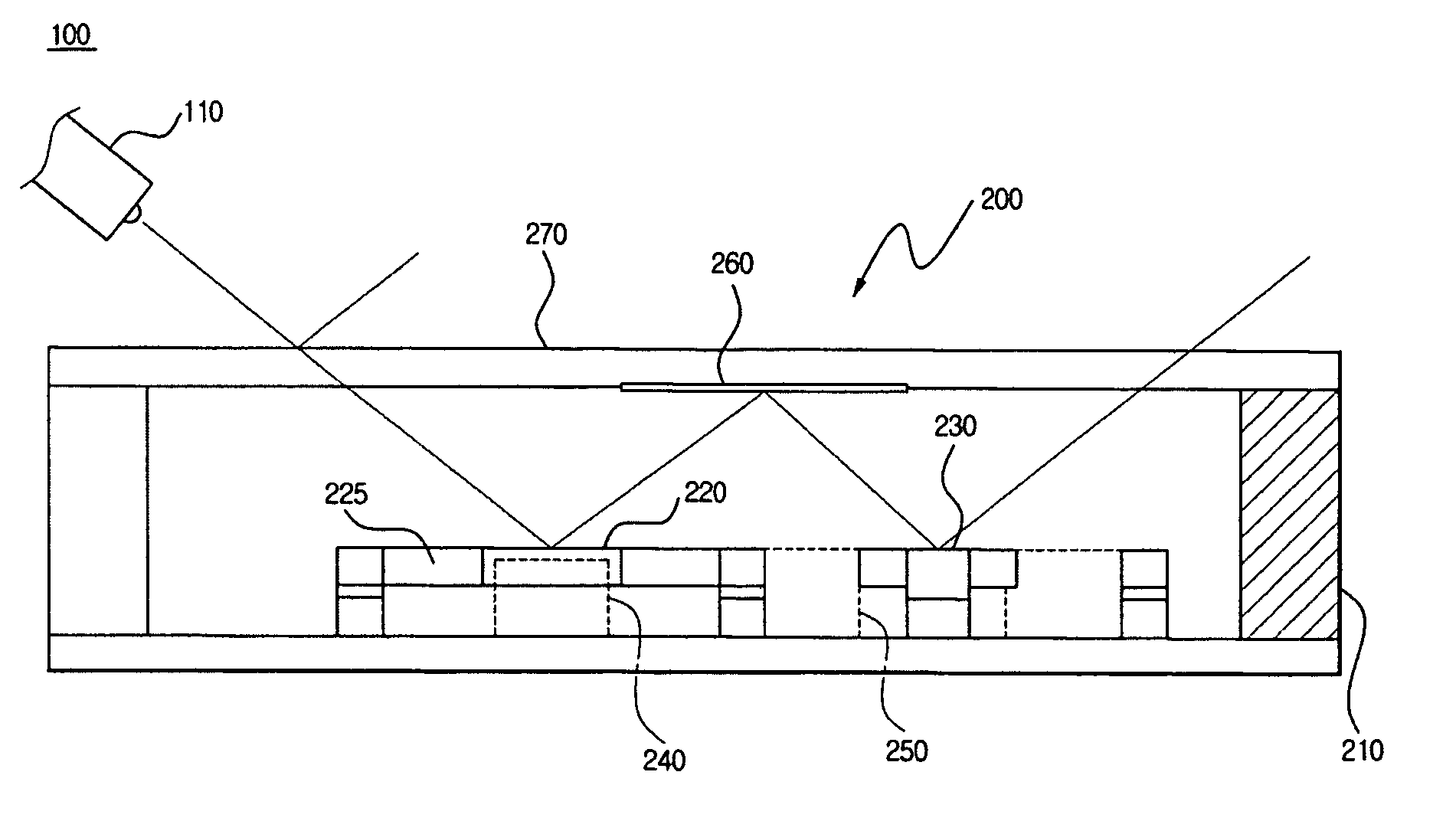
[0053]FIG. 3 illustrates an mirror package optical scanner, according to an embodiment of the present invention, and FIG. 4 illustrates a side view of the same.

[0054] Referring to FIGS. 3 and 4, image equipment using a laser, for example, may include an optical scanner 100, with the optical scanner 100 including a light source 110 and a mirror package 200. The light source 110 may emit light and the mirror package 200 may two-dimensionally divide the scanning / reflecting of the emitted light, with each mirror performing a portion of the required reflecting operations. A modulator may be used to mix light formed of red, green, and blue colors, or combination of other colors, ...


PUM


Abstract

An optical scanner system and method having a light source, a first mirror rotatable along a first torsion axis to reflect light from the light source, a first vibrator to vibrate the first mirror, a second mirror positioned adjacent to the first mirror and rotatable along a second torsion axis different from the first torsion axis, a second vibrator to vibrate the second mirror, and a mirror reflecting the light reflected from the first mirror to the second mirror. In addition, microminiaturization may be further embodied by applying an MEMS technology. Further, a vibrating body may be designed to vibrate with high frequencies by reducing the size and mass of the vibrating body. Through embodiments of the present invention, it is also possible to prevent interference between light entering a mirror package and the finally reflected light.

Description

CROSS-REFERENCE TO RELATED APPLICATIONS [0001] This application claims the benefit of Korean Patent Application No. 10-2005-0083697, filed Sep. 8, 2005, in the Korean Intellectual Property Office, the disclosure of which is incorporated herein by reference. BACKGROUND OF THE INVENTION [0002] 1. Field of the Invention [0003] Embodiments of the present invention relate to an optical scanner changing the path of light. More particularly, embodiments of the present invention relate to a mirror package scanning apparatus having a simple structure and capable of two-dimensional scanning. [0004] 2. Description of the Related Art [0005] An optical scanner is usually used to change the path of a laser, e.g., during the scanning of a two dimensional image. Such an optical scanner may further be easily used for a laser printer, a bar code reader, and the like. In addition, the optical scanner may perform more complicated operations such as complex image processing, e.g., for a laser television...

Claims


Application Information

Patent Timeline
IPC IPC(8): G02B26/08
CPCG02B26/101G02B26/08G02B26/10
Inventor CHO, JIN WOOLEE, HWA SUNKO, YOUNG CHULLEE, JIN HO
Owner SAMSUNG ELECTRONICS CO LTD
Why Eureka
Try Eureka