Bearing support with an instrumented movement and coder for an information recorder unit

a technology of information recorder and supporting body, which is applied in the direction of instruments, mechanical equipment, rotary machine parts, etc., can solve the problems of not always very strict teeth or windows, not insignificant imbalance, and large weight of encoders, and achieves the effect of light weight and easy mounting

Inactive Publication Date: 2007-03-08
AB SKF
View PDF66 Cites 12 Cited by
  • Summary
  • Abstract
  • Description
  • Claims
  • Application Information

AI Technical Summary

Benefits of technology

[0028] Encoders described wherein are particularly light in weight, easy to mount on a rotatin...

Problems solved by technology

The encoder has a mass and an inertia that are relatively high, something which is rarely desirable.
An encoder, the active part of which is of the eccentric type, gives rise to a not insignificant amount of imbalance at high rotational speeds.
Furthermore, the shape of the teeth or of the windows is not always very strict if conventional manufacturing processes such as press cutting are to...

Method used


Image

  • Bearing support with an instrumented movement and coder for an information recorder unit
  • Bearing support with an instrumented movement and coder for an information recorder unit
  • Bearing support with an instrumented movement and coder for an information recorder unit

Examples


Embodiment Construction

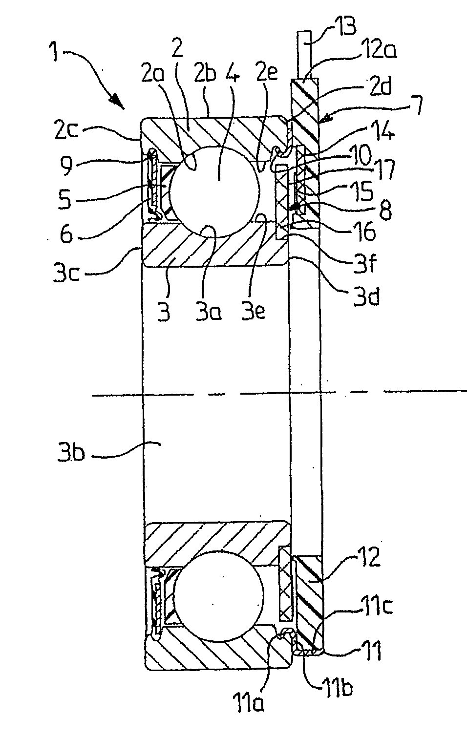
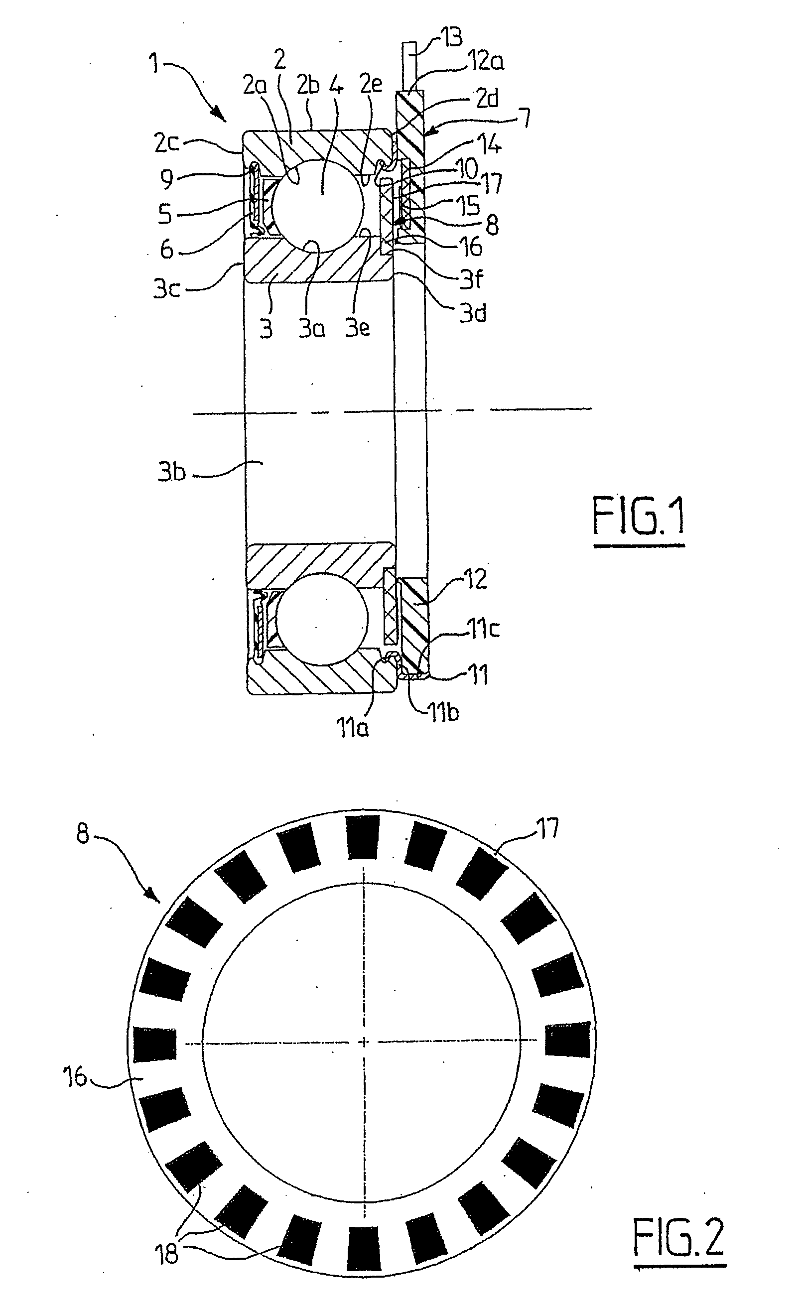
[0035] As illustrated in FIG. 1, the rolling bearing 1 includes an outer ring 2, an inner ring 3, a row of rolling elements 4, in this instance balls, positioned between the outer ring 2 and the inner ring 3 and held by a cage 5, a seal 6 secured to the outer ring 2 and rubbing against the inner ring 3, a sensor 7 secured to the outer ring 2 and an encoder 8 secured to the inner ring 3.

[0036] More specifically, the outer ring 2 will generally be a non-rotating ring, while the inner ring 3 will be used as a rotating ring. However, in some applications it is desirable to gain rotation information about a rotating part. The encoder is then positioned secured to the non-rotating ring while the sensor is mounted secured to the rotating ring. Furthermore, it is perfectly conceivable to provide a sensor secured to the inner ring and an encoder secured to the outer ring, whether the latter be a rotating or a non-rotating ring.

[0037] The outer ring 2 is of solid type, including a toroidal ...


PUM


Abstract

The invention relates to a bearing support with an instrumented movement (1), comprising a non-rotating bush (2), a rotating bush (3), roller elements (4), arranged between the rotating (3) and non-rotating (2) bushes and an information recorder unit, with a sensor (7) and a coder (8), comprising a substrate (16) made from an electrically non-conducting material and a thin layer (17) of electrically-conducting material, supported by the substrate (16). The substrate (16) is fixed in rotation with the rotating bush (3).

Description

BACKGROUND OF THE INVENTION [0001] 1. Field of the Invention [0002] The present invention relates to the field of encoders able to collaborate with a sensor with a view to detecting a movement, particularly the rotational movement of a rotating part with respect to a non-rotating part. [0003] 2. Description of the Relevant Art [0004] Generally an encoder is generally mounted on the rotating part while the sensor is mounted on the non-rotating part, although the set-up is reversed in certain applications. [0005] The sensor is capable of delivering a signal enabling the value of a parameter that is to be measured, such as the displacement, the position, the speed or the angular acceleration of the rotating part to be determined. The active part of the encoder, which collaborates with one or several sensors, includes encoding elements the shape and structure of which depend on the type of sensor with which the encoder works. [0006] In numerous applications, the rotating part is a rotat...

Claims


Application Information

Patent Timeline
IPC IPC(8): F16C41/04F16C19/52G01D5/20G01P3/44G01P3/488G01P3/49
CPCG01D5/202G01P3/443G01P3/488F16C41/008F16C41/007F16C19/06G01P3/49F16C2300/02G01D2205/73G01D2205/775
Inventor GALLION, SAMUELLAUFERON, FRANCK
Owner AB SKF
Why Eureka
Try Eureka