Self adjusting instrument

a self-adjusting and instrument technology, applied in the field of tools, can solve the problems of persistent apical periodontitis, poor treatment quality, poor quality of treatment, etc., and achieve the effects of saving valuable time, improving debridement and disinfection procedures, and effective cleaning of the entire canal

a self-adjusting and instrument technology, applied in the field of tools, can solve the problems of persistent apical periodontitis, poor treatment quality, poor quality of treatment, etc., and achieve the effects of saving valuable time, improving debridement and disinfection procedures, and effective cleaning of the entire canal

US20070054238A1Active Publication Date: 2007-03-08REDENT NOVA LTD

Image

  • Self adjusting instrument
  • Self adjusting instrument
  • Self adjusting instrument

Examples


Embodiment Construction

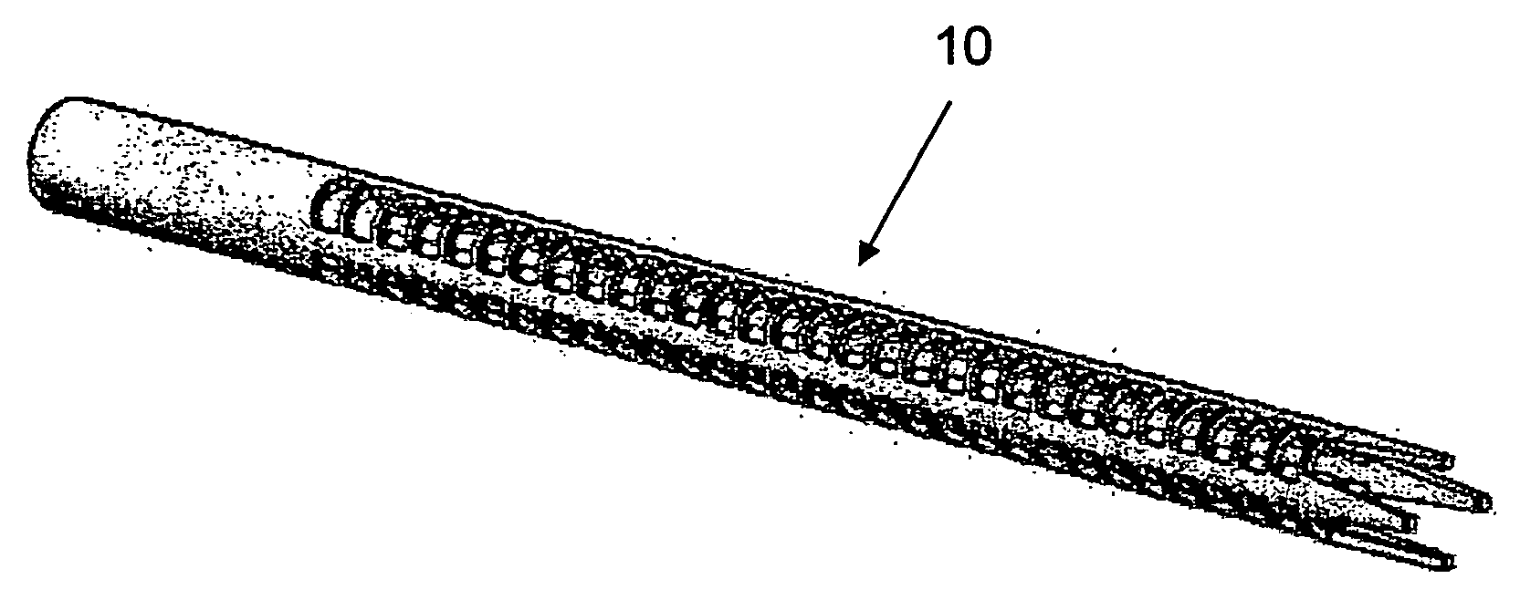
[0065] In general, the channels to be widened and / or cleaned and / or shaped by the instrument of the invention are relatively long and narrow. These channels will be described hereinbelow in terms of a single “longitudinal axis”, which is the line defined by the loci of the center points of the channel along its length, and a multitude of “radial axes”, wherein each such radial axis is defined by a line originating at a point on the longitudinal axis and perpendicular to the longitudinal axis at that point. Rotation of a given radial axis around its origin defines the localized “radial plane”. The direction essentially parallel to the longitudinal direction will be known as the “longitudinal direction” and the direction essentially parallel to one of the radial axes will be known as the “radial direction”. Because the instrument of the invention conforms to the shape of the canal similar terminology will be used to describe the principal axes of the instrument.

[0066] The instrument ...


PUM


Abstract

The invention is an instrument for cleaning and / or shaping and / or widening a channel that exists in or through a solid object. The design of the instrument the superelastic and shape memory properties of the material from which it is made, allow the inner volume enclosed by the instrument, its outer contour, or both to change as a result of the forces exerted upon it while working, thereby shaping the instrument to the three-dimensional contour of the channel. A preferred embodiment of the instrument is an endodontic file for use in the cleaning, shaping, and widening stages of a root canal procedure.

Description

[0001] This application is the National Stage of International Application No. PCT / IL2005 / 000086 filed on Jan. 24, 2005, which claims priority to Israeli application no. 160074 filed on Jan. 26, 2004, and which application(s) are incorporated herein by reference.FIELD OF THE INVENTION [0002] The present invention is related to the field of tools. Specifically the present invention relates to an instrument for cleaning and / or shaping and / or widening a channel, existing in or through a solid object. BACKGROUND OF THE INVENTION [0003] Publications and other reference materials referred to herein, including references cited therein, are incorporated herein by reference in their entirety and are numerically referenced in the following text and respectively grouped in the appended Bibliography which immediately precedes the claims. [0004] There are many situations in which it is required to use an instrument for cleaning out and / or shaping and / or widening a channel that exists in or passe...

Claims


Application Information

Patent Timeline
08 Mar 2007
Publication
US20070054238A1
IPC
A61C5/02; A61C3/02
CPC
A61C5/023; A61C3/02; A61C5/42
Inventors
HOF, REPHAEL; TEPEROVICH, EHUD