
Lateral implant system and apparatus for reduction and reconstruction

a technology of lateral implants and implants, applied in the field of lateral implant systems, can solve the problems of splinting fractured bones, exacerbated familiar problems, and strong and often eccentric forces, and achieve the effect of enhancing healing and quick return to function

Inactive Publication Date: 2007-03-08
BIOMED EST
View PDF11 Cites 36 Cited by
  • Summary
  • Abstract
  • Description
  • Claims
  • Application Information

AI Technical Summary

Benefits of technology

[0028] The implant does not have to be inserted into the alveolar crest completely, but only with the base plates that show into the bone direction. Then augmentation material, resorbable or not resorbable, can be augmented and the shape of the augmented site is given by the baseplates; then a fibrin-membrane (made from the patients blood) or any other membrane (artificial, cow, pig, other origins, etc), can be put over the exposed baseplates and enhance healing.
[0030] Lateral implants distribute the forces to bone areas which are strong (highly mineralized), as opposed to prior art pins that come out of the bone on areas that are not so strong (low mineralization areas) and where screws would not adequately hold. Of course, the present system may be used in combination with conventional screws for fixation. The open slots of the present system promote woven bone formation, especially in osteoporotic bone. Woven bone is created in addition to the existing cortical bone, so there is a more bone in the end. The pins used herein may be completely smooth so infection can not catch easily as in screw implants.

Problems solved by technology

Fixation and splinting of fractured bones has long been a challenge for medical and dental practitioners.
These problems are particularly true in oral or maxilo-facial area, where chewing can exert strong and often eccentric forces on the mandible and / or maxilla.
These forces have long made it a challenge to achieve early return to function for a patient suffering from a broken mandible or maxilla.
In particular, familiar problems are even further exacerbated in the case of the edentulous mandible.
Chewing with a full denture is suboptimal and frequently problematic, since fixation of the denture to the lower mandible and gums is seldom fully sufficient and typically allows the denture to “float” in the oral cavity during chewing.
Screw-type implants are problematic in that in order to function properly, they require a certain depth of bone to be available.
For the patient who fractures an endentulous mandible, there does not currently exist a fully optimized, durable, economic, relatively easy to install solution that promotes rapid mending of the fractured mandible while further promoting a rapid return to full function.
Although such surgeries may be life saving, the resulting large facial defects have a serious cosmetic impact for the patient.
Experience has shown that during or after radiation therapy conventional screw implants have suffered very low success rates, due to implant rejections caused by osteonecrosis, osteomyelitis and the like.
Previously, only prolonged waiting periods of up to 24 months will lower the failure rate experienced with conventional screw implants.
For the patient with a substantial cosmetic defect, this waiting period is difficult.
The high failure rate is caused by BMU osteosystems which remodel internal bone structure under normal circumstances being destroyed by the radiation and do not regenerate quickly.
This has the disadvantage of degrading the structural integrity of the bone in which the anchors are placed.
Other problems with prior art devices include the pin coming out of the bone on areas that are not so strong (low mineralization areas) and where prior art screws would not adequately hold.
Maintaining the stability of enossal implants with respect to the bone into which they are placed is often a clinical problem.
However, most of the mobility is caused by overloading the peri-implant bone.
None of those efforts has yet resulted in an actual measurable clinical result, and there has been no overwhelming success in clinical practice, as it takes many weeks to months before the newly formed bone truly mineralizes and becomes capable of bearing a load.

Method used


Image

  • Lateral implant system and apparatus for reduction and reconstruction
  • Lateral implant system and apparatus for reduction and reconstruction
  • Lateral implant system and apparatus for reduction and reconstruction

Examples


Embodiment Construction

[0078] The following description of the preferred embodiment(s) is merely exemplary in nature and is in no way intended to limit the invention, its application, or uses.

[0079] Long Bone Fixation

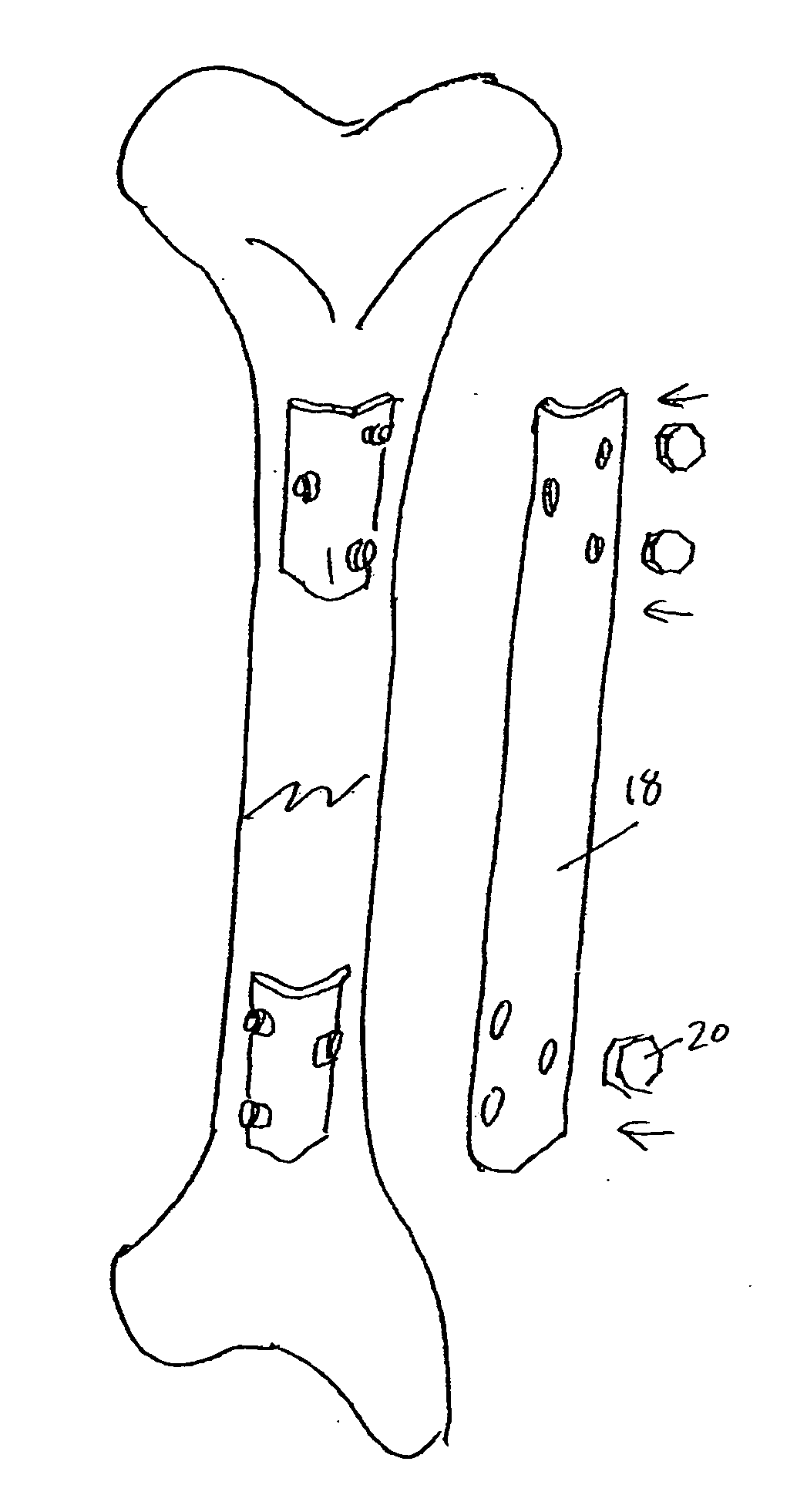
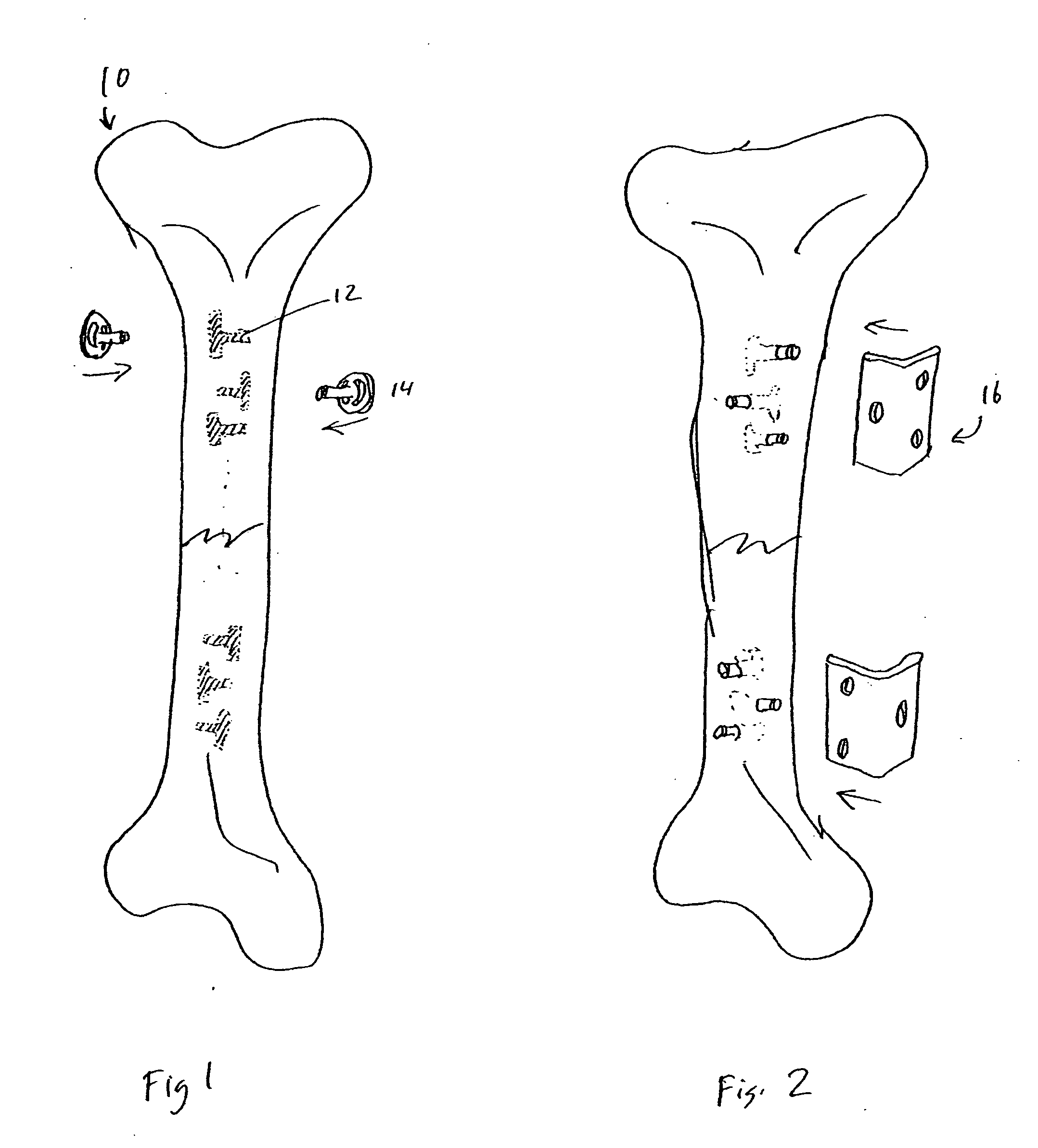
[0080] Referring to the figures where like reference numbers indicate like elements, a long bone such as tibia 10 presenting with a fracture 8 depicted in FIG. 1. Also depicted are basal implants 14, described in greater detail below. They have the common characteristic of having a base plate and a perpendicular rod. In installation, the orthopedic surgeon would cut T-shaped slots 12 in the bone. Advantageously, multiple slots at each anchor site may be cut and oriented such that the basal implants will insert and mount at various angles.

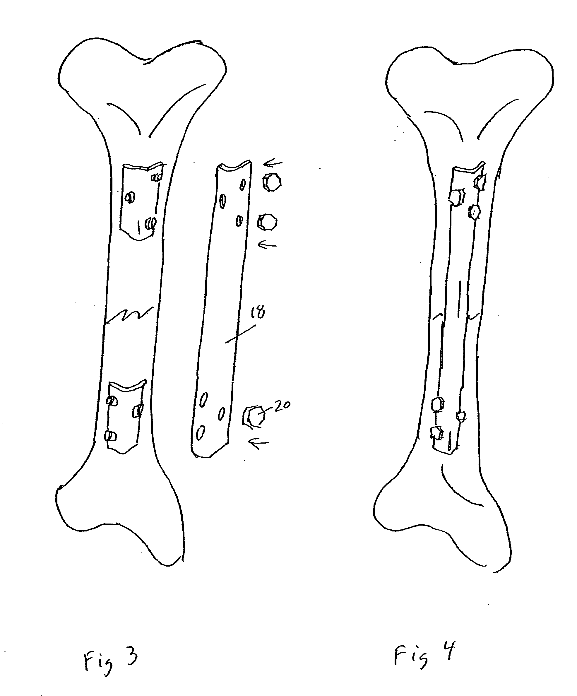
[0081] As depicted in FIG. 2, the basal implants are inserted into the slots 12 and a top of a post of the basal implant extends beyond the surface of the bone and outwards to receive further hardware. The implants may optionally be secured with screws as ...


PUM


Abstract

A bone fixation apparatus and method includes basal implants dimensioned to be installed in bone through lateral insertion into a T-shaped slot. The implants serve as anchors for mounting plates to be placed on either side of a fracture. The mounting plates or anchors may be a mount to which a stabilizing fixation rod, plate, prosthesis, dental prosthesis or other mesiostructure is attached.

Description

CROSS-REFERENCE TO RELATED APPLICATIONS [0001] This application claims priority to U.S. Provisional Patent Applications 60 / 709,232 filed Aug. 18, 2005; 60 / 709,233 filed Aug. 18, 2005; 60 / 740,098 filed Nov. 28, 2005 and 60 / 757,194 filed Jan. 6, 2006; and to German Patent Application No. 20 2006 006 920.8 filed Apr. 25, 2006; German Patent Application No. 20 2006 010 202.7 filed Jun. 27, 2006; German Patent Application No. 20 2006 008 702.8 filed May 24, 2006; and German Patent Application No. 20 2006 003 922.8 filed Mar. 7, 2006.BACKGROUND OF THE INVENTION [0002] 1. Field of the Invention [0003] The present invention is in the medical field of reduction and fixation of long bone fractures, human mandible fractures and anchoring prosthetics and maxillofacial implants, in particular implants following surgical resections. [0004] 2. Related Art [0005] Fixation and splinting of fractured bones has long been a challenge for medical and dental practitioners. There has been a constant need ...

Claims


Application Information

Patent Timeline
IPC IPC(8): A61F2/30
CPCA61C8/0018A61B17/663A61B17/666A61C8/001A61B17/80A61B17/8071A61B17/84A61B17/68
Inventor IHDE, STEFAN
Owner BIOMED EST
Learn More