
Methods of treating deposition process components to form particle traps, and deposition process components having particle traps thereon

a technology of deposition process components and particle traps, which is applied in the direction of vacuum evaporation coatings, chemistry apparatuses and processes, coatings, etc., can solve the problems of affecting the desired properties of films, and affecting the adhesion of film surfaces

Inactive Publication Date: 2007-03-15
HONEYWELL INT INC
View PDF0 Cites 29 Cited by
  • Summary
  • Abstract
  • Description
  • Claims
  • Application Information

AI Technical Summary

Problems solved by technology

Problems can occur in deposition processes if particles are formed, in that the particles can fall into a deposited film and disrupt desired properties of the film.
Although some of the textured surfaces have been found to reduce particle formation, problems exist with various of the textured surfaces.
The surfaces of the beads can have relatively poor adhesion for re-deposited material entering a particle-trapping region, and can thus degrade performance of the particle-trapping region.

Method used


Image

  • Methods of treating deposition process components to form particle traps, and deposition process components having particle traps thereon
  • Methods of treating deposition process components to form particle traps, and deposition process components having particle traps thereon
  • Methods of treating deposition process components to form particle traps, and deposition process components having particle traps thereon

Examples


Embodiment Construction

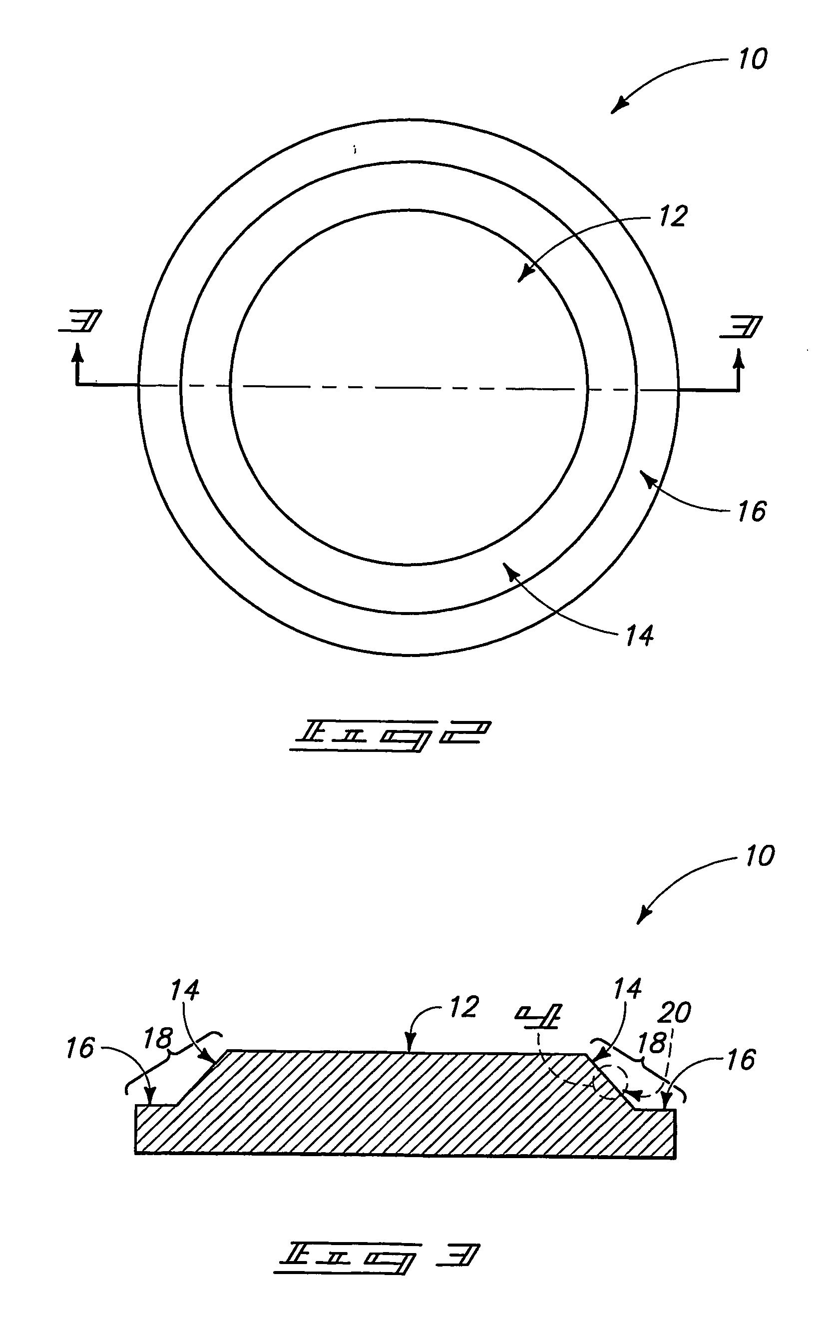
[0031] The invention encompasses particle-trapping regions which can be formed on one or more surfaces of a PVD component, and methods of forming the particle-trapping regions. The particle-trapping regions can be utilized for trapping materials which deposit on the component during a deposition process.

[0032] The particle-trapping regions are formed by treating one or more surfaces of the PVD component with bead blasting, and in some aspects also with machine tooling. If the treated component is a sputtering target, the treated surfaces can include any non-sputtered surfaces, such as, for example, sidewall surfaces, flange surfaces and / or non-sputtered surfaces along a sputtering face.

[0033] Projections formed with machine tooling can be considered to correspond to a macro-scale roughness, and roughening accomplished by bead blasting can be considered to correspond to a micro-scale roughness. Thus, the invention can include patterns which have one or both of macro-scale and micro...


PUM

PropertyMeasurementUnit
repeat distanceaaaaaaaaaa

Abstract

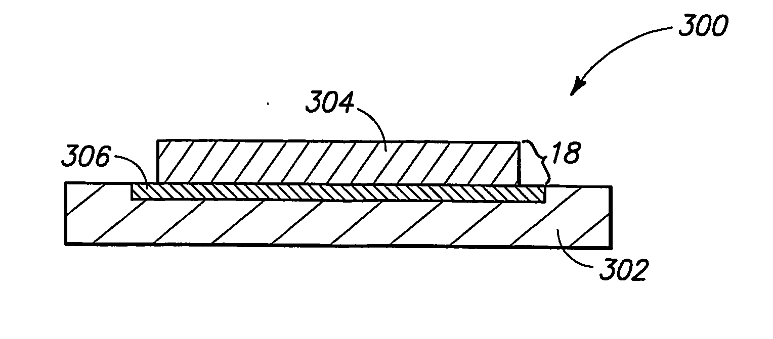
The invention includes methods for forming particle traps along surfaces of PVD components, and comprises PVD components having particle traps thereon. The invention can include utilization of highly soluble media for bead-blasting and / or can include utilization of metallic materials as bead-blasting media. The invention can also include formation of an insert along regions of a backing plate where particle traps are desired, with the insert being of a composition which has better particle-trapping properties than the backing plate.

Description

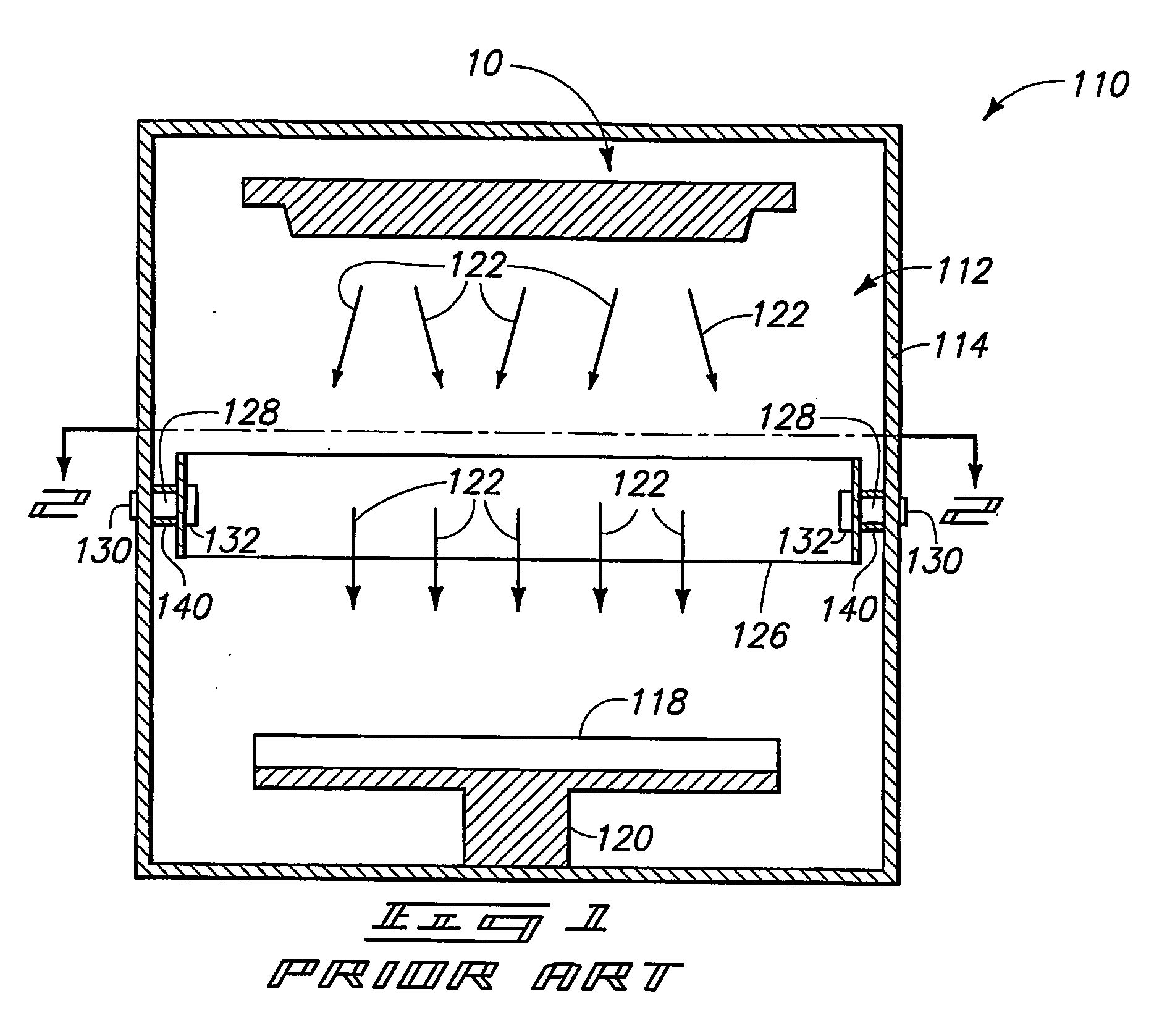
RELATED APPLICATION DATA [0001] This application claims priority to U.S. Provisional Application 60 / 502,689, which was filed on Sep. 11, 2003; and also claims priority to U.S. Provisional Application 60 / 543,457, which was filed on Feb. 9, 2004.TECHNICAL FIELD [0002] The invention pertains to methods of forming particle traps along regions of physical vapor deposition (PVD) process components, such as, for example, sputter targets. BACKGROUND OF THE INVENTION [0003] PVD methods are utilized for forming films of material across substrate surfaces. PVD methods can be utilized in, for example, semiconductor fabrication processes to form layers ultimately utilized in fabrication of integrated circuitry structures and devices. [0004] A PVD operation is described with reference to a sputtering apparatus 110 in FIG. 1. Apparatus 110 is an example of an ion metal plasma (IMP) apparatus, and comprises a chamber 112 having sidewalls 114. Chamber 112 is typically a high vacuum chamber. A target...

Claims


Application Information

Patent Timeline
Patent Type & Authority Applications(United States)
IPC IPC(8): B32B37/00
CPCB24C1/003B24C1/06H01J2237/022C23C14/3414H01J37/3435C23C14/3407
Inventor KIM, JAEYEONPHELAN, TERRY J.KARDOKUS, JANINE K.SAYLES, SCOTT R.
Owner HONEYWELL INT INC
Learn More