
Method and device for filling zones situated in hollows or between tracks with a viscous product on a printed circuit board and apparatus using such a device

a technology of printed circuit board and filling zone, which is applied in the direction of printed circuit aspects, electrical devices, coatings, etc., can solve the problems of affecting the complete filling of the product, generating cycle times that are incompatible with mass production, and particularly striking problems

Inactive Publication Date: 2007-03-15
NOVATEC SA
View PDF1 Cites 13 Cited by
  • Summary
  • Abstract
  • Description
  • Claims
  • Application Information

AI Technical Summary

Benefits of technology

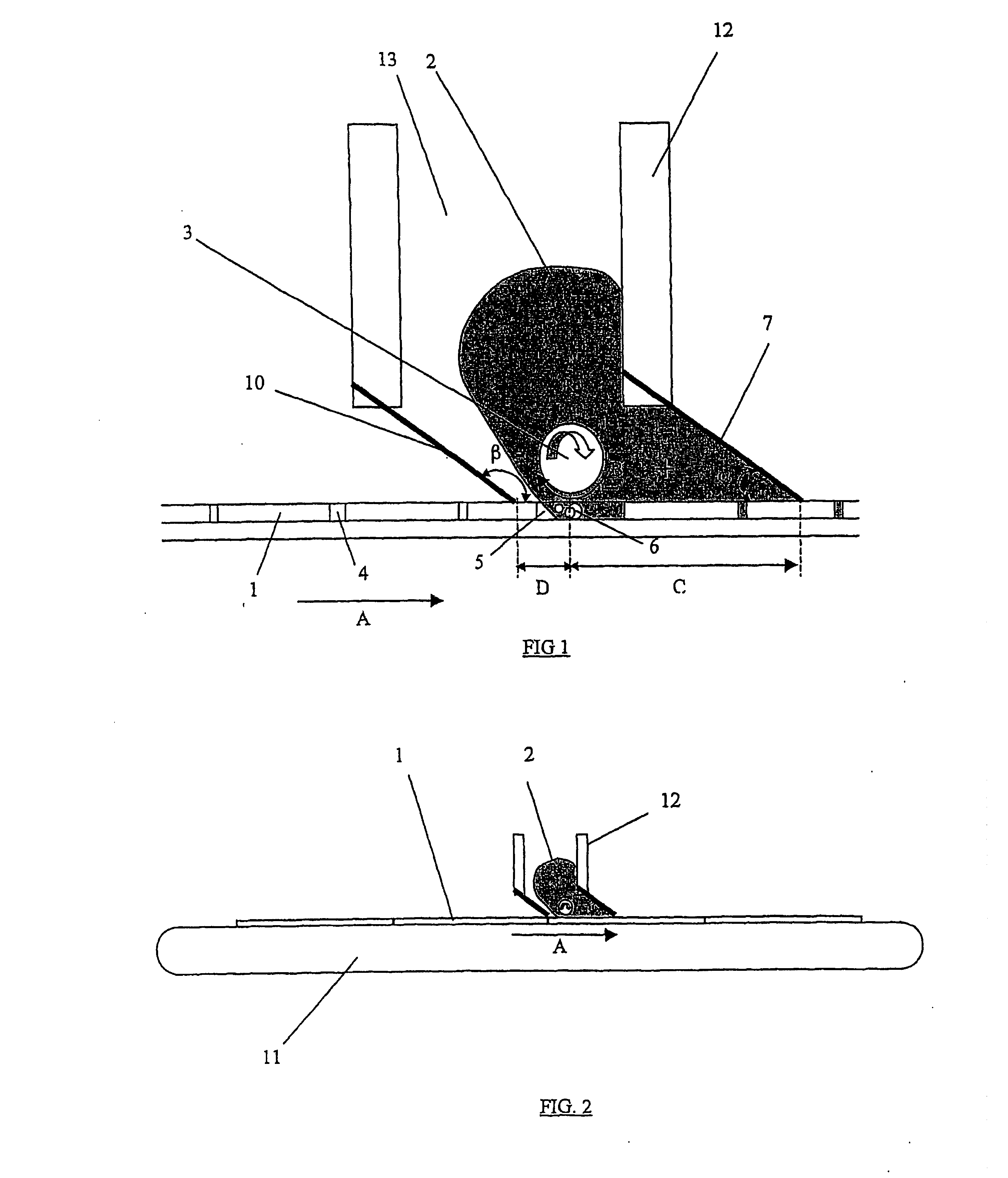
[0014] Beforehand at the step of displacing the product in the areas of the zones to be filled, the method of the invention proposes also to make the zone to be filled impermeable from all entry of exterior gas to the zone, by spreading the product at the surface of the substrate in order to isolate the zones to be filled from the exterior gas and make the product available. Thus, the impermeability is assured by maintaining the zone to be filled covered with product from the beginning of the filling up to the scraping of the excess or the adjustment of the thickness of the product at the surface of the substrate so that the filling product is displaced in the areas of the zone to be filled avoiding all later contact with exterior gas to the zone to be filled. At no time, from the spreading of the filling product up to the adjustment of the thickness, which can go up to the scraping of the total excess, should the zone to be filled be in contact with gas coming from the exterior of the zone to be filled.
[0019] According to another characteristic of the invention, the displacing of the product at the point of the zone to be filled is obtained by a hydrodynamic effect, and preferably, by the hydrodynamic effect of a roller in rotation of which the axis is perpendicular to the movement of the substrate with respect to the device and parallel to the substrate and so that the tangential movement of the roller at the point of the zone to be filled is opposed to the direction of relative displacement of the substrate with respect to the device. In this manner, the adherence of the viscous product on the roller generates, by a hydrodynamic effect, a displacement of the filling product. The displacement increases as the distance with respect to the roller diminishes. At the surface of the roller, the speed of the product is equal to the tangential speed of the roller. Then it diminishes as one moves away from the roller. This reduction depends on the rheology of the filling product. In all cases, the roller will be arranged at a sufficiently small distance from the substrate so that hydrodynamic effect will be noticeable, for example such that the speed of the product is greater than or equal to fifty percent of the tangential speed of the roller at the point of the zone to be filled. Preferably, one will avoid contact between the roller and the substrate in order to, on the one hand, eliminate all risk of mechanical friction and, on the other hand, to avoid disturbing the hydrodynamic effect.
[0022] The direction of rotation of the roller, such that its tangential movement at the point of the zone to be filled is opposed to the direction of displacement of the substrate, will permit, on the one hand, to accumulate the filling product by way of the hydrodynamic effect, towards the scraping element in order to create a confined zone of surge pressure between the roller and the scraping element situated downstream from the roller and, on the other hand, to create a circulation of filling product at the point of the zones to be filled from the zone of surge pressure toward the zone of reduced pressure situated upstream from the roller.
[0023] The surge pressure created in the confined zone downstream under the concerted action of the displacing element and of the scraping element allows compensating for the effect of re-drawing and of scooping of the product by the scraping element, the redrawing being called the trail effect. Also, another advantageous characteristic of the invention comprises adjusting or selecting the speed of rotation and / or the diameter of the roller for displacing of the filling product in a fashion to adjust the differential pressure of the confined downstream zone of surge pressure with respect to the upstream zone of reduced pressure, allowing control of the spillover of product under the scraping element at the point of the zones to be filled and to compensate for the trail effect, of the aforementioned scraping element in order to be able to cause a deposition over thickness strictly opposing the zones in hollows.
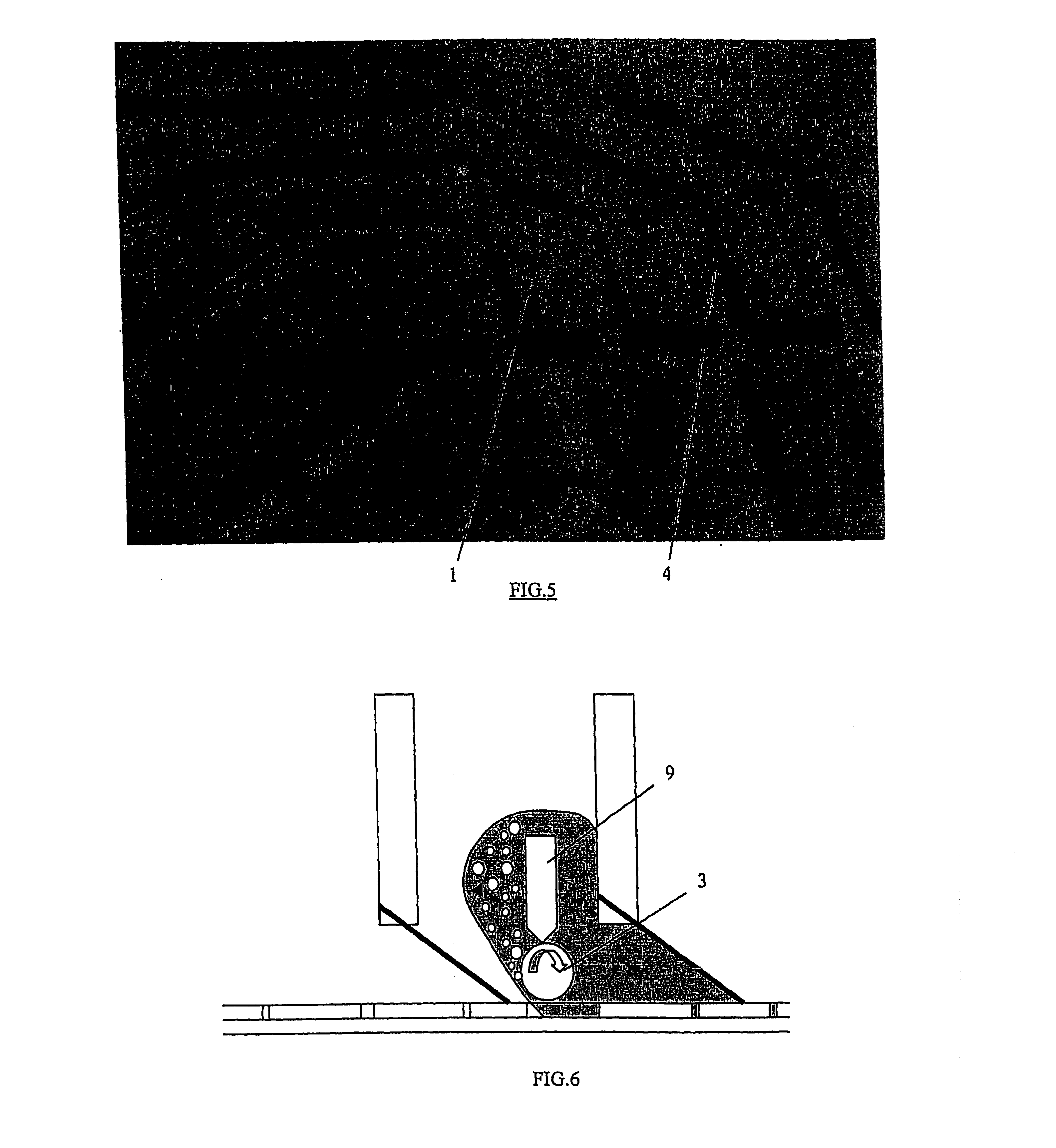
[0024] According to another characteristic of the invention, in order to avoid that the bubbles extracted by the roller forming the displacing element are redrawn in the zone to be filled in hollows, it can be prudent to place a scraper at the surface of the roller situated in the filling head and ideally, tangentially on the upper part of the roller. Thus, when the roller rotates, the bubbles drawn by the movement of the product are blocked by this scraper and do not then have another alternative except to re ascend to the surface of the filling product as a result of the difference of density of the gas with respect to the product. In fact, the scraper has the purpose of interrupting the hydrodynamic effect, to locally eliminate the displacement of the product. It is notable that the gas is naturally evacuated as a result of the difference of pressure existing between the downstream and the upstream of the displacing element according to the direction of displacement of the substrate.

Problems solved by technology

There are two types of problems with these devices of the prior art: the first resides in the fact that in certain zones situated in hollows and closed on the other face, the air remains trapped and inhibits the product from completely filling them.
Obviously, these multiple passages generate cycle times incompatible with mass production.
This problem is particularly striking when one uses a transfer roller.
Otherwise the filling of the blocked hole cannot be completely achieved.
Furthermore, achievement of the vacuum is extremely difficult to obtain and to maintain on substrates of large dimension with possible surface irregularities.
A major disadvantage of this type of devices resides in the fact that the product transferred by the roller is redrawn at the back of the roller.
By contrast, this technique is not applicable to filling with a more or less pasty liquid product of zones in hollows closed on the other face possibly extending long lengths, that is to say several millimeters even several centimeters or decimeters and possibly presenting an aspect ratio, defined by the depth of the zone relative to the surface divided by the smallest aperture dimension, less than one.
In fact, no device for evacuating the air, present in zones in hollows, is provided.
The use of this device for filling zones in closed hollows could lead to compressing the air in the zone in hollows at the time of the passage when the device faces the zone but may permit in no case a total filling, free of air bubbles.

Method used


Image

  • Method and device for filling zones situated in hollows or between tracks with a viscous product on a printed circuit board and apparatus using such a device
  • Method and device for filling zones situated in hollows or between tracks with a viscous product on a printed circuit board and apparatus using such a device
  • Method and device for filling zones situated in hollows or between tracks with a viscous product on a printed circuit board and apparatus using such a device

Examples


Embodiment Construction

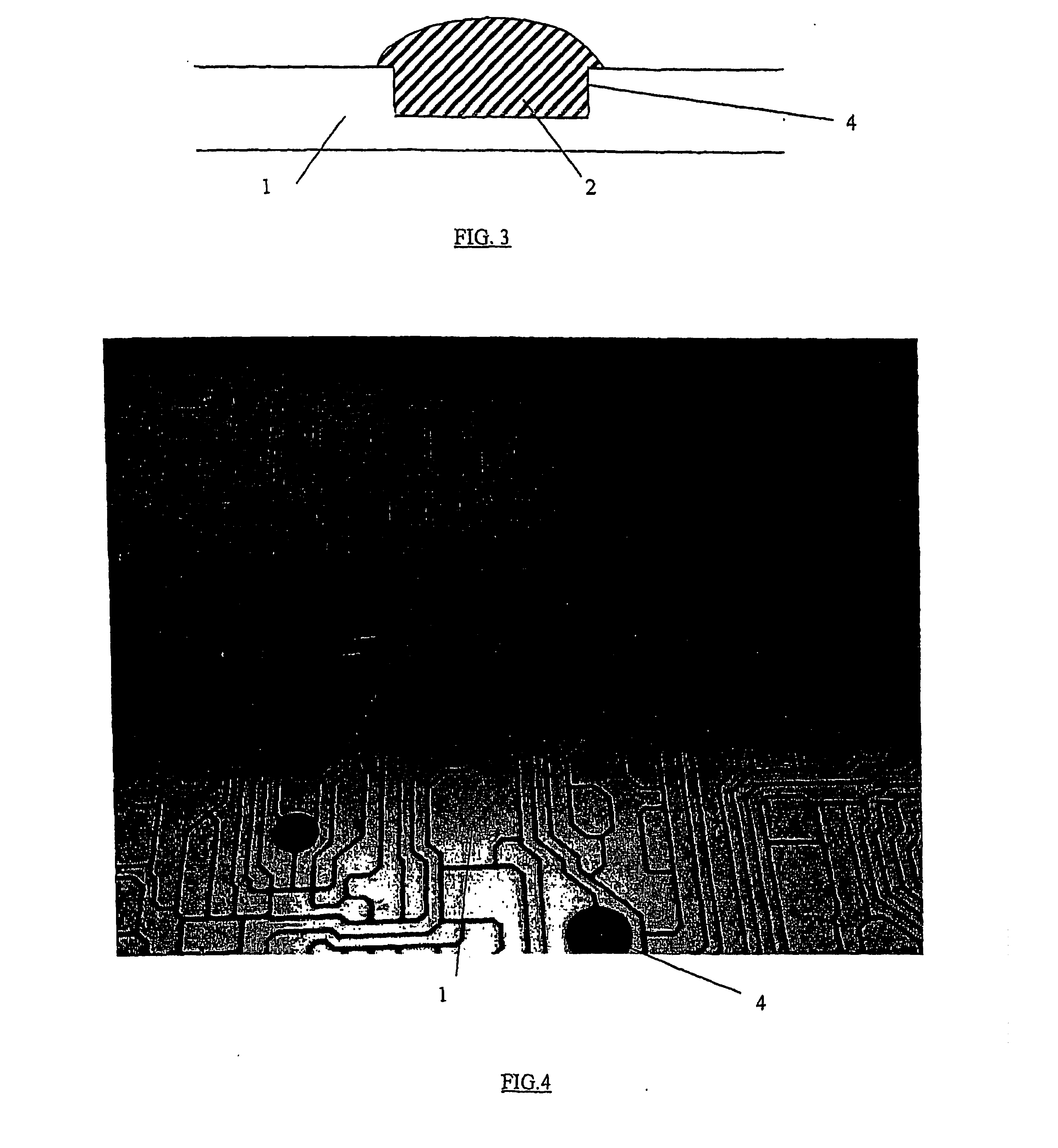
[0010] The present invention aims to fill without air bubbles and in over thickness, strictly at the point of zones in hollows directly on the printed circuit without screen or silk screen printing block by a more or less viscous liquid or paste product, of the inter-track or of the zones situated in hollows with respect to the surface of the substrate and more particularly of the zones closed on the opposing face and of which the length can be very long and / or having an aspect ratio defined by the depth of the zone relative to the surface of the substrate divided by the smallest aperture dimension, less than or equal to one, as for example zones situated between copper tracks.

[0011] According to the invention, the process of direct filling without air bubbles and in over thickness of inter-tracks or of zones situated in hollows with respect to this surface of a substrate or of a printed circuit by a viscous product is remarkable in that it comprises: [0012] displacing the filling ...


PUM

PropertyMeasurementUnit
Angleaaaaaaaaaa
Lengthaaaaaaaaaa
Thicknessaaaaaaaaaa

Abstract

The invention relates to a method and device for filling areas located in hollows (4) which do not open out onto the surface of a substrate (1) without a mask or silk screen. According to the invention, said method consists in associating the following objects according to the order of the direction of relative displacement of a head (12) of a filling product (2) in relation to the substrate (1) i.e. a spreading element (10) for the product to be filled (2) on the surface of the substrate (1); an element for displacing (3) the filling product (2) in the area to be filled (4); an element (7) for adjusting the thickness or raking off the excess filling product (2) such that the above-mentioned filling product (2) remains constantly in contact with the area to be filled (4) from the beginning of the filling operation until raking off of the excess product.

Description

FIELD OF APPLICATION [0001] The present invention relates to a device for filling zones situated in hollows with respect to a surface, with a more or less viscous liquid product, by extraction of the air or of the gas present in the zones in hollows and by replacement with a filling product. Generally these zones are of long length, narrow, and deep. By way of example, the invention finds its application in the realization of power printed circuits such as those used in the automobile sector. In fact, there exist applications for which substrates having conductive tracks, of copper for example, and having a thickness greater than 100 microns (typically on the order of 400 microns) are used. In these applications, it is necessary to fill the inter-track zones with a dielectric product, this filling having to be without bubbles in order to obtain the optimal electrical characteristics and overthickness strictly at the point of the zones in hollows. Furthermore, the inter-track zones a...

Claims


Application Information

Patent Timeline
IPC IPC(8): B23K31/00B23K1/20B05C3/18H05K3/28H05K3/40
CPCB05C3/18H05K3/28H05K2203/0143H05K2201/09881H05K2203/0139H05K3/4053H05K3/40
Inventor BOURRIERES, FRANCISKAISER, CLEMENTCICERO, ANTONIONOVELLO, OSVALDO
Owner NOVATEC SA
Learn More