Optical termination system

a technology of optical termination and termination system, which is applied in the field of optical termination system, can solve the problems of temporary interruption of service to all users, and achieve the effect of shortened blackout period caused by switching

Inactive Publication Date: 2007-03-15
KDDI CORP
View PDF7 Cites 63 Cited by
  • Summary
  • Abstract
  • Description
  • Claims
  • Application Information

AI Technical Summary

Benefits of technology

[0008] An optical termination system according to still another embodiment of the invention includes an optical transmitter / receiver to connect with a plurality of ONUs through an optical transmission line, a first OLT electronic unit to communicate with the plurality of ONUs using the optical transmitter / receiver, the first OLT electronic unit having a control information storage to store control information of the plurality of ONUs, a standby OLT electric unit having a storage to store the control information to be transferred from the first OLT electric unit, and a controller to control switching from the first OLT electric unit to the standby OLT electric unit. The present invention can switch from a working OLT to a standby OLT much quicker compared to prior art. Since the standby OLT can use the control information of the working OLT, a blank period caused by the switching is shortened.

Problems solved by technology

Replacement of an OLT causes temporary interruption of service to all users under the OLT.

Method used


Image

  • Optical termination system
  • Optical termination system
  • Optical termination system

Examples


Embodiment Construction

[0014] Explanatory embodiments of the invention are explained below in detail with reference to the drawings.

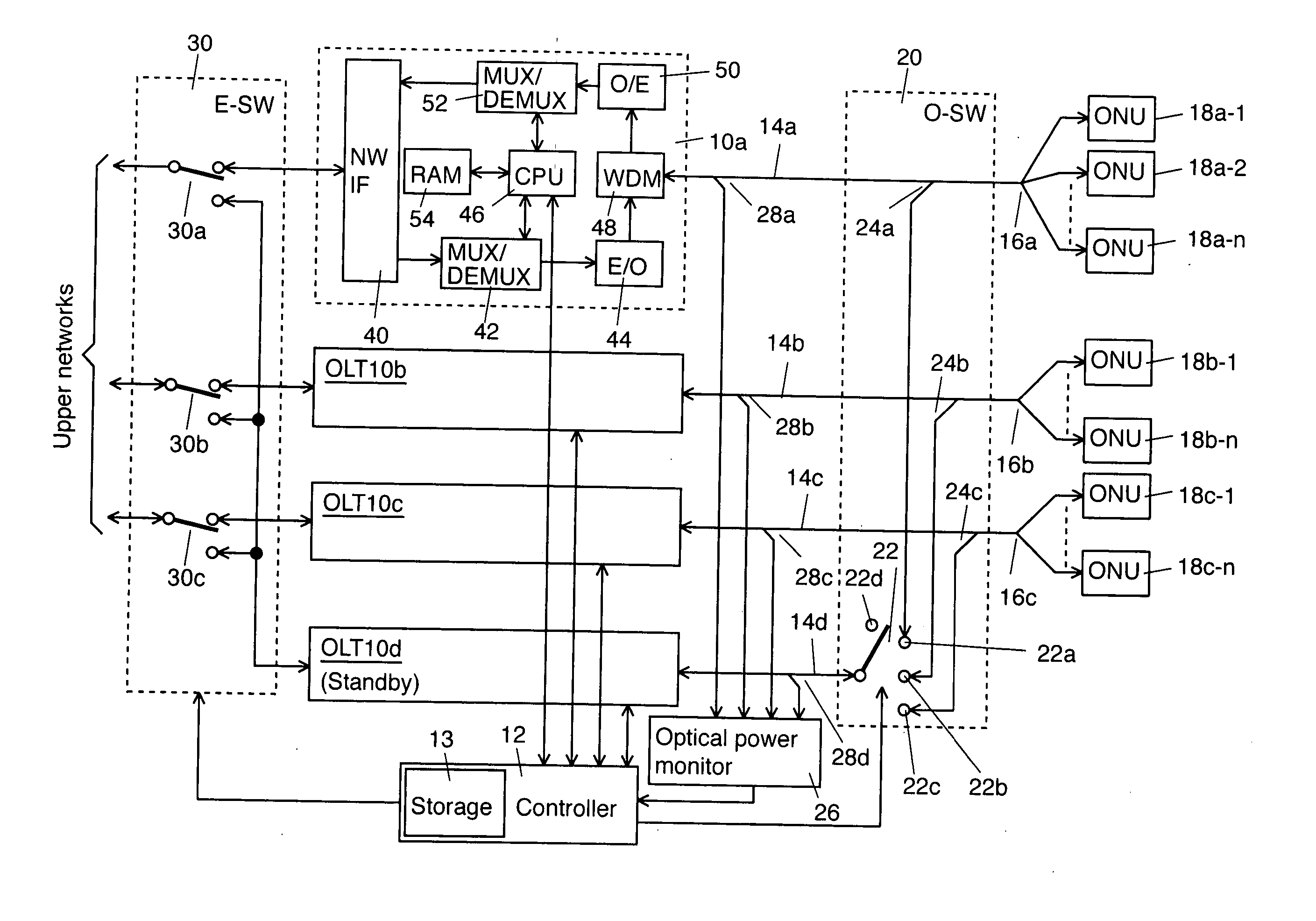
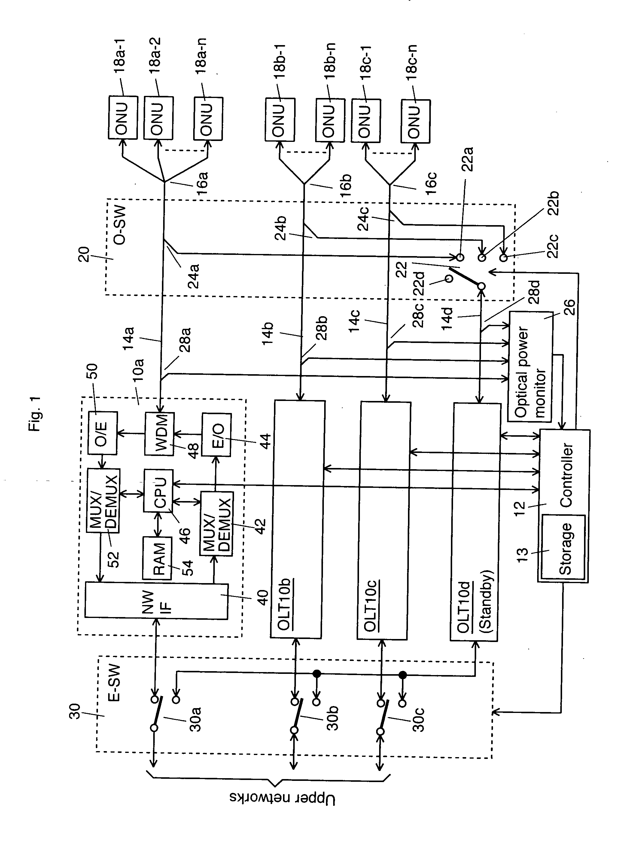
[0015]FIG. 1 shows a schematic block diagram of a first exemplary embodiment according to the invention. In this embodiment, three working OLTs 10a, 10b, and 10c, a standby OLT 10d or protection OLT, and a controller 12 to switch one of the working OLTs 10a to 10c having a fault to the standby OLT 10d are disposed on a different slot in the same rack respectively. The OLTs 10a to 10d correspond to optical line terminals in claims. The controller 12 includes a storage 13 to temporally store the control information to be transferred to the standby OLT 10d from one of the OLTs 10a to 10c having a fault.

[0016] An optical input / output port of the OLT 10a connects to a plurality of ONUs 18a-1 to 18a-n through a first PON transmission line including an optical fiber 14a and an optical coupler 16a. Similarly, an optical input / output port of the OLT 10b connects to a plurality of ON...


PUM


Abstract

An optical termination system is provided. The optical termination system includes a working Optical Line Terminal (OLT) that communicates with a plurality of Optical Network Units (ONUs) near end users through an optical transmission line. The OLT includes a control information storage to store control information of the plurality of ONUs. In addition, the optical termination system includes a standby OLT, which includes a storage to store the control information to be transmitted from the working OLT. Furthermore, the optical termination system includes a controller that controls switching from the working OLT to the standby OLT.

Description

CROSS REFERENCE TO RELATED APPLICATIONS [0001] This application claims priority to Japanese Patent Application No. 2005-220033, filed on Jul. 29, 2005, the entire contents of which are incorporated herein by reference. FIELD OF THE INVENTION [0002] This invention relates to an optical termination system having a redundant configuration in an optical transmission system. BACKGROUND OF THE INVENTION [0003] A Passive Optical Network (PON) system is an optical transmission system to connect an Optical Line Terminal (OLT) at a central office to a plurality of Optical Network Units (ONUs) at end user's sides through passive optical elements which consist of optical fibers and optical splitters (See, for instance, Japanese Laid-Open patent application JP2005-175599). [0004] A PON system is now widely used not only as Internet access lines but also as a system to provide broadcasts, data communications, and data. [0005] When a PON system is used for broadcasting and / or telephone services, i...

Claims


Application Information

Patent Timeline
Patent Type & Authority Applications(United States)
IPC IPC(8): H04J14/00H04B10/03H04B10/032H04B10/079H04B10/27H04B10/272H04L12/44
CPCH04B10/032H04J14/0226H04J14/0282H04J14/0291H04J14/0232H04Q11/0067H04Q2011/0081H04J14/0247H04J14/0252H04J14/0297
Inventor TANAKA, KEIJI
Owner KDDI CORP
Why Eureka
Try Eureka