
Foot prosthetic and methods of use

a foot and prosthetic technology, applied in the field of prosthetic devices, can solve problems such as limiting their energy producing capacity, and achieve the effects of improving the energy efficiency of prosthetic feet, reducing energy required, and facilitating us

Inactive Publication Date: 2007-03-15
RGT UNIV OF MICHIGAN
View PDF1 Cites 61 Cited by
  • Summary
  • Abstract
  • Description
  • Claims
  • Application Information

AI Technical Summary

Benefits of technology

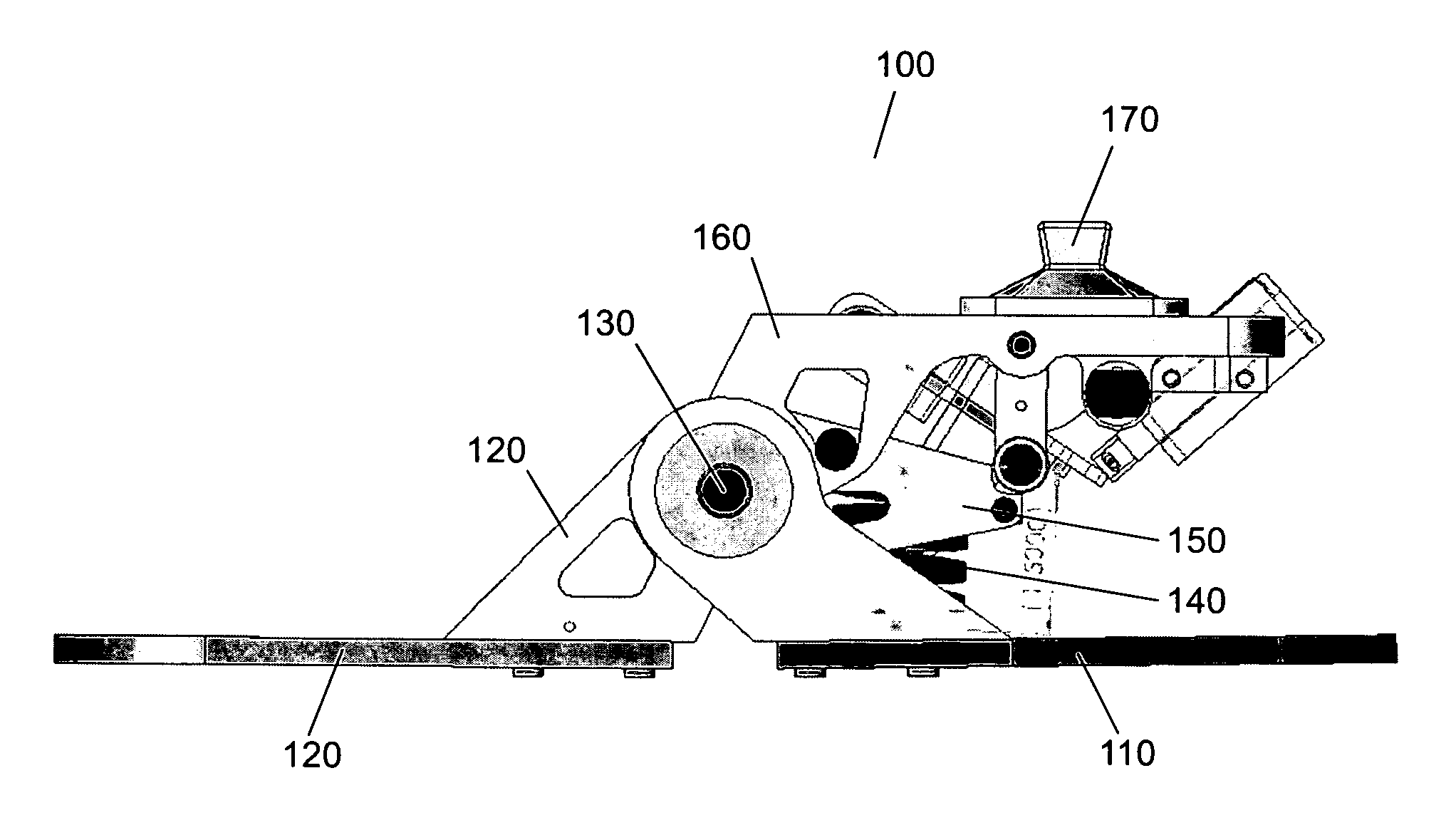
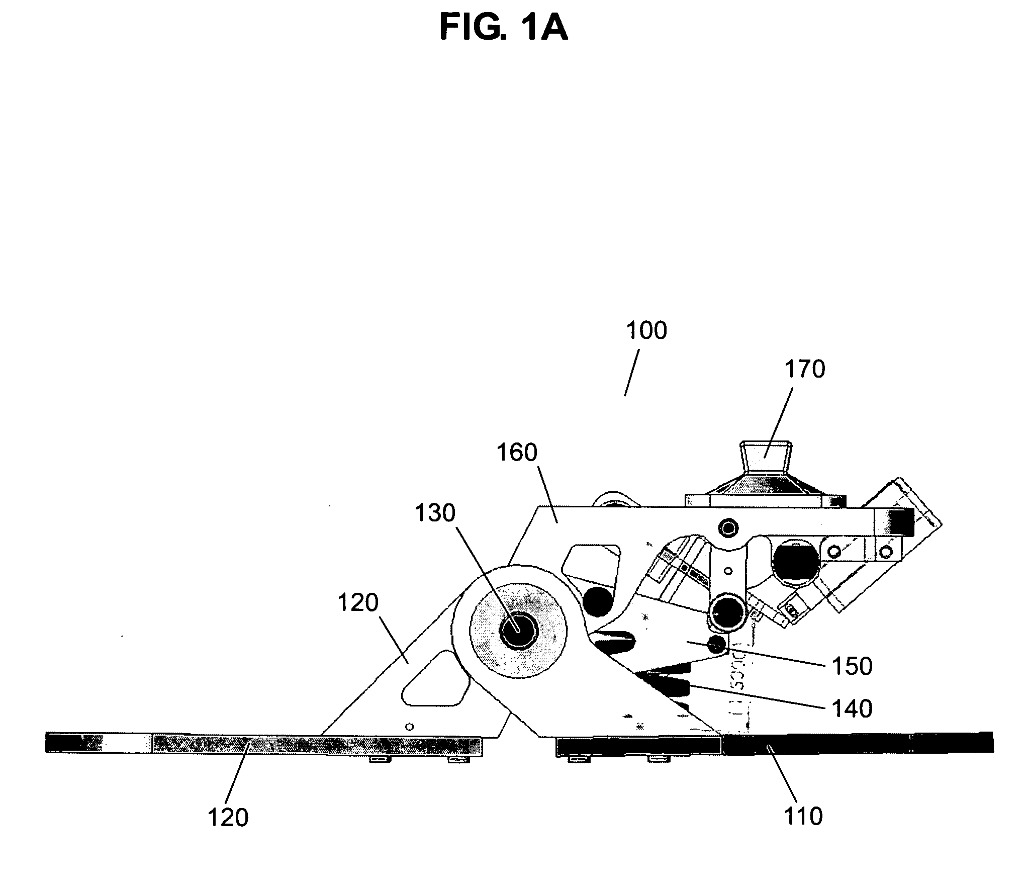
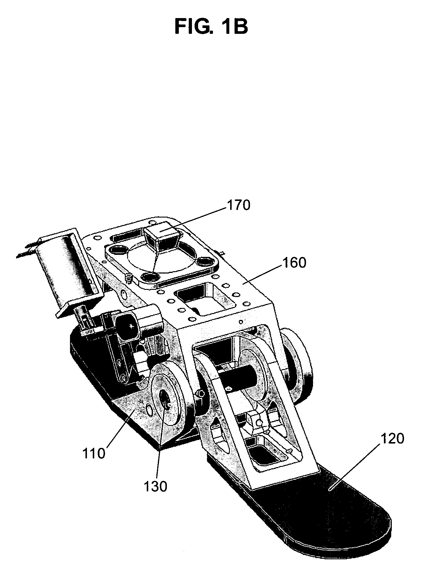
[0004] The present invention relates generally to prosthetic devices. In particular, the present invention describes intelligent (e.g., microprocessor controlled) foot prostheses configured to actively store and release energy associated with walking. The foot prostheses of the present invention reduce the energy required during ambulation for amputees requiring foot prostheses. The present invention provides systems, methods, and kits comprising intelligent foot prosthetic devices, employing controlled energy storage and release technologies. Such technology allow for improving the energy efficiency of prosthetic feet by incorporating mechanistic control to adjust the timing of energy release from an elastic mechanism. Unlike currently available prosthetic feet, the controlled energy storage and release technology allows walking, for example, with greater energy efficiency and comfort.
[0009] In certain embodiments, the present invention provides a foot prosthesis having therein a microprocessor controlling a latch spring, wherein the microprocessor regulates the amount of compression the latch spring undergoes upon bearing of weight, and wherein the microprocessor regulates the amount of release the latch spring undergoes upon a reduction in amount of weight bore by the latch spring. In some embodiments, the microprocessor controls the timing of when the latch spring compresses or decompresses.
[0013] In some embodiments, the toe plate and heel plate is constructed of a carbon fiber and resin composite. In some embodiments, the prosthetic device is designed for placement within a shoe. In some embodiments, the microprocessor controlled latch disengagement permits the release of energy collected at the heel plate upon the toe plate.

Problems solved by technology

Young healthy traumatic amputees can tolerate this increase reasonably well, but most amputations are for vascular reasons (e.g., from complications associated with diabetes), and many of these patients have cardiocirculatory problems that limit their energy producing capacity.

Method used


Image

  • Foot prosthetic and methods of use
  • Foot prosthetic and methods of use
  • Foot prosthetic and methods of use

Examples


example i

[0040] This example describes the use of a foot prosthetic simulator designed to demonstrate the conceptual advantage of a foot prosthesis utilizing an intelligent design. The simulator was worn on the lower extremity of an able-bodied subject, such that it immobilized the ankle and allowed the attachment of a variety of alternative artificial foot surfaces. It was similar to an ankle foot orthosis, except that it allowed able-bodied persons to simulate prosthetic gait. The primary attachment designed was a spring device which satisfied the mechanical requirements of a controlled-release storing prosthesis. A secondary attachment was designed, to roughly emulate a conventional energy-storing prosthesis. These attachments allowed a single human subject to compare the experience of walking with conventional and controlled-release energy storage, in both unilateral and bilateral configurations. Moreover, these conditions allowed comparison with the same subject's able-bodied gait. The ...

example ii

[0047] This example describes a proposed research protocol utilizing the prosthesis simulator. A simple set of experiments will be used to test the feasibility of controlled-release energy storage. These experiments will be performed on 12 able-bodied young human subjects. Subjects will be recruited by advertisement, with their informed consent and safety ensured. The experiments will test and compare subjects' gait with and without the prosthesis simulator, with and without controlled-release of stored energy. The outcome measures are the metabolic energy expenditure of at a given speed, as well as and ground reaction forces. The subjects will perform multiple walking trials at a given speed of 1 m / s, a slow and comfortable walking speed. These trials will be performed once overground in order to measure ground reaction forces, and then repeated on a treadmill to measure metabolic energy expenditure. The overground trials will also involve measurement of joint motions by a Optotrak...

example iii

[0053] This example describes an experiment with a prosthesis simulator. Humans actively push off with the trailing leg just before and during the double support phase of walking. Push-off compensates for the energy lost as the leading leg performs negative work during the transition between steps (see, e.g., Donelan, J M, et al. J Exp. Biol. 205: 3717-3727, 2002; herein incorporated by reference in its entirety). Simple models predict that the energy used in walking is strongly linked to the mechanics of this step-to-step transition; pushing off just before double support can theoretically reduce the step-to-step transition work by a factor of four (see, e.g., Kuo, A D. J. Biomech. Eng. 124: 113-120, 2002; herein incorporated by reference in its entirety).

[0054] Lower-limb amputees have a reduced capacity for ankle pushoff during walking (see, e.g., Whittle, M W. Gait Analysis: An Introduction, 1996; herein incorporated by reference in its entirety) contributing to a 20-30% greate...


PUM


Abstract

The present invention relates generally to prosthetic devices. In particular, the present invention describes intelligent (e.g., microprocessor controlled) foot prostheses configured to actively store and release energy associated with walking. The foot prostheses of the present invention reduce the energy required during ambulation for amputees requiring foot prostheses.

Description

[0001] The present application claims priority to U.S. Provisional Patent Application Ser. No. 60 / 705,019 filed Aug. 3, 2005, which is herein incorporated by reference in its entirety.FIELD OF THE INVENTION [0002] The present invention relates generally to prosthetic devices. In particular, the present invention describes intelligent (e.g., microprocessor controlled) foot prostheses configured to actively store and release energy associated with walking. The foot prostheses of the present invention reduce the energy required during ambulation for amputees requiring foot prostheses. BACKGROUND OF THE INVENTION [0003] Over one million persons in the U.S. live with the absence of a limb (National Center for Health Statistics, 1993). Many of these are lower limb amputees, and an estimated 173,000 use an artificial foot or leg (National Center for Health Statistics, 1994). Below-knee amputees make up the majority of this group, and together with above-knee amputees comprise over 80% of a...

Claims


Application Information

Patent Timeline
IPC IPC(8): A61F2/66A61F2/70
CPCA61F2/66A61F2/68A61F2002/5055A61F2002/5072A61F2002/5073A61F2002/7635A61F2002/6642A61F2002/665A61F2002/6671A61F2002/704A61F2002/705A61F2002/6621A61F2/70
Inventor KUO, ARTHURCOLLINS, STEVEN
Owner RGT UNIV OF MICHIGAN
Learn More