Combined sensor and its fabrication method

a technology of combined sensor and fabrication method, which is applied in the direction of acceleration measurement using interia force, turn-sensitive devices, instruments, etc., can solve the problems of individual differences in the vibrational sensor elements, the publication does not disclose any combined sensor structure, and the inability to achieve the desired optimum vibrational characteristics, etc., to achieve the desired optimum vibration characteristics, improve the detection sensitivity of the sensor, and high tolerance to shock

Inactive Publication Date: 2007-03-22
HITACHI LTD
View PDF0 Cites 78 Cited by
  • Summary
  • Abstract
  • Description
  • Claims
  • Application Information

AI Technical Summary

Benefits of technology

[0015] Further, since the vibrating sensor elements constituting the vibration units are supported independent of each other, mutual interference of vibrations based on difference in characteristics, that is, individual difference of the vibrating sensor elements can be eliminated. Further, even if there is the individual difference in the vibrating sensor elements, the characteristics of the vibrating sensor elements can be adjusted independently without mutual interference since each of the vibrating sensor elements includes vibration detection means capable of monitoring the vibration state, that is, the frequency of vibration properly and voltage application means for varying the rigidity of beams of the vibrating sensor element to adjust the frequency of vibration. In other words, the combined sensor of the present invention can adjust the individual difference of the vibrating sensor elements constituting the combined sensor easily

Problems solved by technology

However, the publications do not disclose any combined sensor structure and measures for detecting accelerations in two axes applied in the in-plane direction of the substrate together with the angular rate (yaw rate) applied around the axis in the thickness direction of the substrate.
Accordingly, the vibrating sensor elements of this angular rate sensors are difficult to get the desired optimum vibration forms and amplitudes.
The reason thereof is that the vibrating sensor elements are connected to each other by means of the beams as described above and the vibrations thereof interfere with each other.
However, it is considered that the sensor disclosed in the publication has the structure that the individual difference in the vibrating sensor elements caused by error in the fabrication is not allowable.
Further, since the vibration

Method used


Image

  • Combined sensor and its fabrication method
  • Combined sensor and its fabrication method
  • Combined sensor and its fabrication method

Examples


embodiment 1

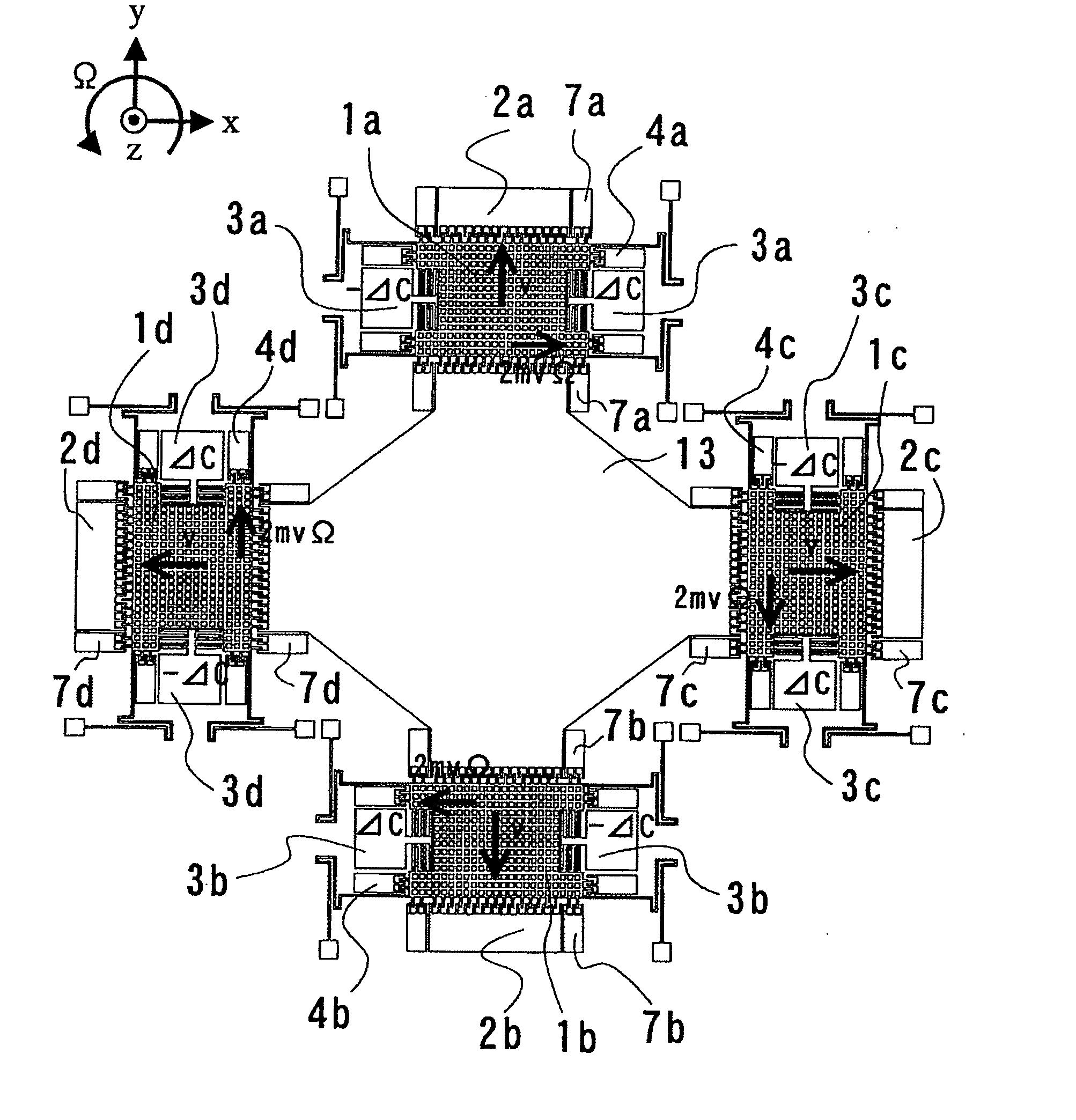
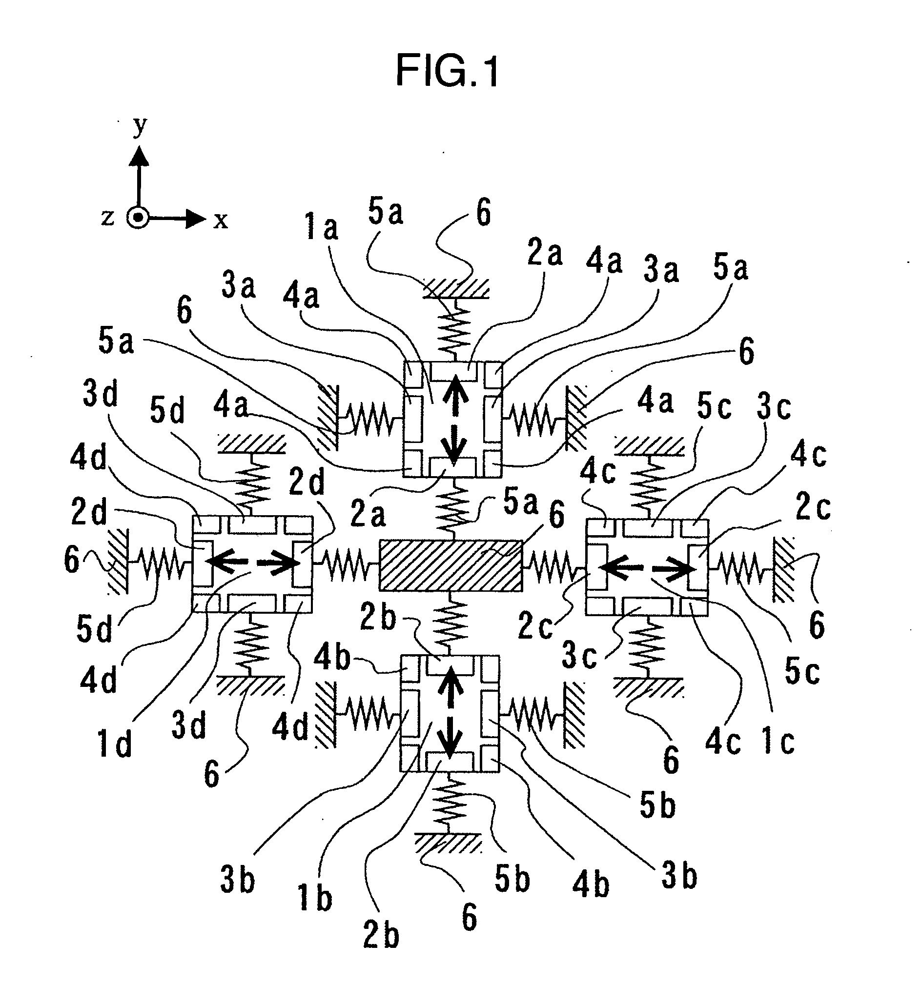
[0031]FIG. 1 is a schematic diagram illustrating a sensor structure of a combined sensor according to the present invention. In FIG. 1, vibrating sensor elements 1a, 1b, 1c and 1d that are sensor elements constituting the combined sensor are shown. The vibrating sensor elements have the same structure. Accordingly, structure and operation of the combined sensor according to the present invention are now described with reference to the vibrating sensor element 1a.

[0032] The vibrating sensor element 1a is supported in the vibratile state in the x- and y-axis direction in the plane and in the z-axis direction outside of the plane by means of four springs 5a. This reason is that one ends of the springs 5a are connected to anchorages 6 constituting fixing parts connected to a supporting substrate. Other vibrating sensor elements 1b, 1c and 1d are also supported in the same manner. The vibrating sensor element 1a includes vibration generation means 2a disposed opposite to each other in t...

embodiment 2

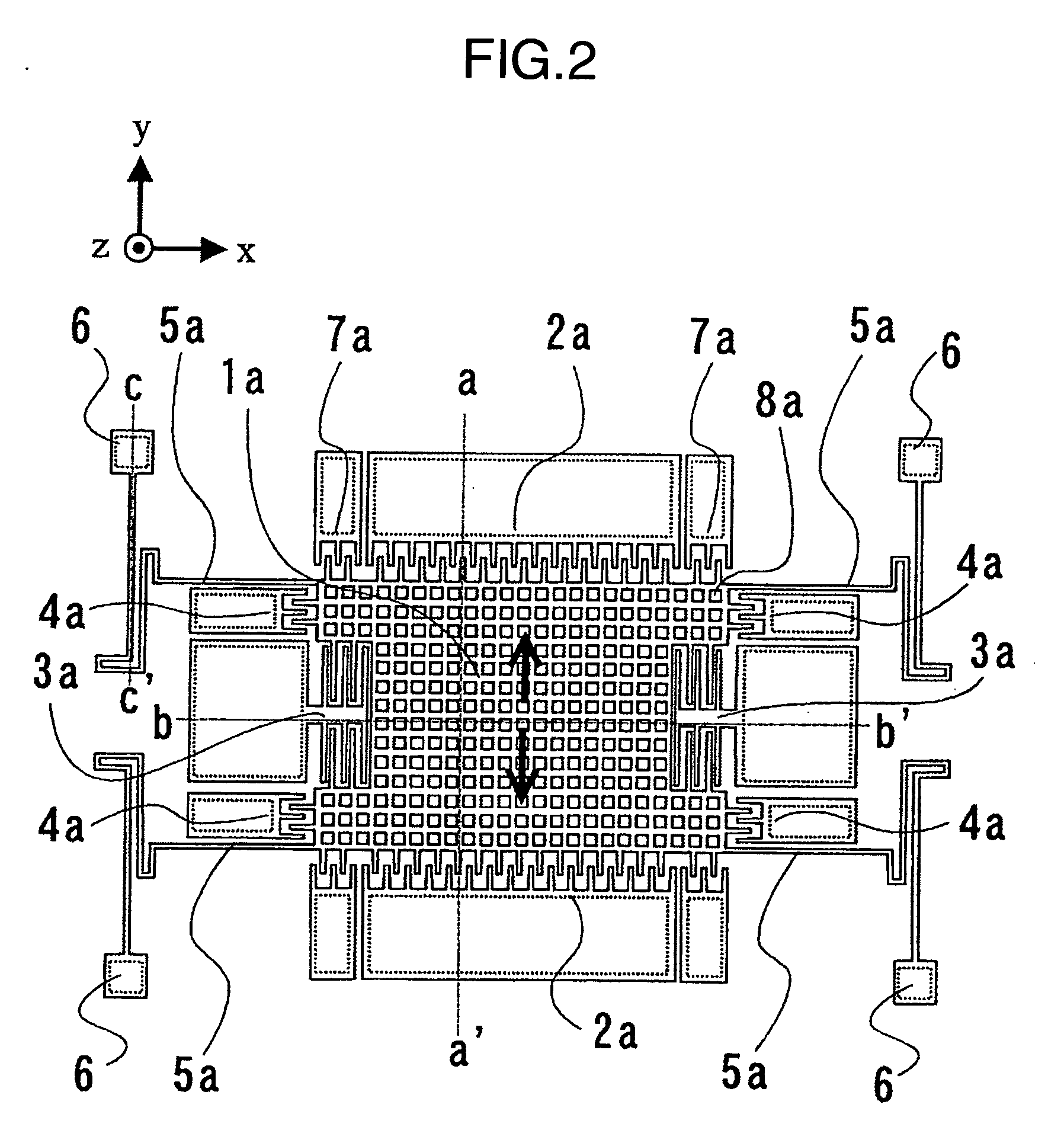
[0057]FIG. 7 is a top view showing a vibrating sensor element 1a constituting a combined sensor according to a second embodiment of the present invention. The vibrating sensor element 1a is formed by dry-etching of a silicon-on-insulator (SOI) substrate in the same manner as that in the first embodiment. Different structure from the first embodiment is described. In the second embodiment, vibration separating plates 14a are disposed in order to separate the vibration in the x-axis direction and the vibration in the y-axis direction clearly. X-axis-directional spring beams 15ax that are springs in the x-axis direction and y-axis-directional spring beams 15ay that are springs in the y-axis direction are connected to the vibration separating plates 14a. As shown in FIG. 7, 4 x-axis-directional spring beams 15ax and 2 y-axis-directional spring beams 15ay are connected to one vibration separating plate 14a. Further, through-holes 8a are formed in the vibration separating plates 14a and a...

embodiment 3

[0060]FIG. 9 is a top view showing a vibrating sensor element 1a constituting a combined sensor according to a third embodiment of the present invention. The third embodiment is structured on the basis of the second embodiment. That is, the third embodiment includes the vibration separating plates 14a. The third embodiment is different from the second embodiment in that the detection means 3a of the comb structure formed in the vibrating sensor element 1a is removed and instead there are provided a pair of vibration adjustment means 4a disposed opposite to each other and 4 vibration detection means 7a disposed on the side of the vibration adjustment means 4a. Other structure is the same as that of the vibrating sensor element 1a of the second embodiment. Accordingly, the vibration principle of the vibrating sensor element 1a and the detection principle of the angular rate and the accelerations in the third embodiment are the same as the second embodiment. Four vibrating sensor eleme...


PUM


Abstract

A sensor structure using vibrating sensor elements which can detect an angular rate and accelerations in two axes at the same time is provided. 2 sets of vibration units which vibrate in out-of-phase mode (tunning-fork vibration) and include four vibrating sensor elements of the approximately same shape supported on a substrate in a vibratile state are provided and the vibrating sensor elements are disposed so that vibration axes of the vibration units cross each other at right angles. Each of the vibrating sensor elements includes a pair of detection units and adjustment units for adjusting a vibration frequency. The vibrating sensor elements constitute a combined sensor having supporting structure for supporting the vibrating sensor elements independently so that the vibrating sensor elements do not interfere with each other.

Description

BACKGROUND OF THE INVENTION [0001] The present invention relates to a vibrating sensor element formed on a substrate and more particularly to a vibrating sensor element constituting a sensor for detecting an angular rate (yaw rate) in one axis applied around an axis in the thickness direction of the substrate and accelerations in two axes applied in the in-plane direction of the substrate and a combined sensor using the vibrating sensor elements. [0002] In order to detect the angular rates applied in the two axial directions in the plane and around the axis in the thickness direction of the substrate, an angular rate sensor structure in which a vibrating sensor element is applied is disclosed in JP-A-11-64002. This publication discloses an integrated structure including vibrating sensor elements disposed in respective sides of a polygon and connected to each other by means of beams. The connected vibrating sensor elements are supported only by a post disposed in the center and float...

Claims


Application Information

Patent Timeline
IPC IPC(8): G01P15/08G01C19/56G01C19/574G01C19/5747G01P15/125G01P15/18H01L29/84
CPCG01C19/5719G01P15/0802G01P15/18G01P15/14G01P15/097G01P2015/082G01C19/56
Inventor AKASHI, TERUHISAOKADA, RYOJIHAYASHI, MASAHIDESUZUKI, KENGO
Owner HITACHI LTD
Why Eureka
Try Eureka