System and method for heat pump oriented zone control

a technology of a heat pump and a zone control, which is applied in the direction of ventilation systems, heating types, instruments, etc., can solve the problems of insufficient temperature control in the various other regions of the building or home, the inability to provide adequate temperature control for individual rooms and areas, and the inability to adapt to the needs of the individual room or area, so as to achieve the optimal operation of heating and air conditioning equipment, the effect of increasing the capacity of the system

Active Publication Date: 2007-03-22
ARZEL ZONING TECH
View PDF17 Cites 41 Cited by
  • Summary
  • Abstract
  • Description
  • Claims
  • Application Information

AI Technical Summary

Benefits of technology

[0025] In accordance with an embodiment of the present invention, an electronic controller has been designed to optimize the operation of heating and air conditioning equipment. The electronic controller refines control of the equipment by bringing on only specific subsystems of the heating and cooling equipment, depending on the demand from the environmental sensors, the outside air temperature, the temperature of the air leaving the equipment, and the electric utility efficiency programs. The electronic controller allows the available airflow to be concentrated to the areas where there is a current demand for heating, cooling, or ventilation by controlling a set of air-driven zone dampers.
[0026] Embodiments of the present invention provide the ability to choose between more distinct operating modes for the heating and cooling equipment than has typically been contemplated in the past. Embodiments of the present invention provide algorithms to incorporate humidification and dehumidification equipment and techniques that have not typically been a part of a zoning system.
[0027] In accordance with an embodiment of the present invention, a plain English “setup wizard” is provided as part of the controller which allows HVAC installers to configure the system quickly and easily for any system. That is, the controller is a non-proprietary controller that is designed to be configured for and useable with any standard forced air system. In accordance with an embodiment of the present invention, simple and inexpensive standard heat / cool thermostats are used on predefined zones 2 through 4 to make installation easier (e.g., single stage thermostats). Zones 2-4, using simple thermostats, depend more on the controller for zone control. That is, the simple single stage thermostats can only tell the controller if its zone needs heating or cooling. The simple thermostats cannot tell the controller how much heating or cooling is needed or that a zone still needs more heating or cooling. Embodiments of the present invention allow installers to use any thermostat, either heat pump or heat / cool on a predefined zone 1 (e.g., a smarter more complex multi-stage thermostat with emergency or auxiliary heat capability, or a simple thermostat as used on zones 2-4). As a result, the installer is able to tale advantage of certain advanced features built into today's modern thermostats. Installers may also use wireless, auto changeover, single- or two-stage thermostats, or any thermostat that provides installer with the level of control which they desire.
[0028] In accordance with an embodiment of the present invention, when a call for heating or cooling is started, an electronic controller monitors the temperature of the air leaving the heating or cooling equipment (i.e., the Leaving Air Temperature). The electronic controller monitors the change over unit time in the LAT temperature. Any given piece of HVAC equipment may produce a finite amount of heating and cooling. Therefore, a temperature profile of the LAT will start with a steep curve and then flatten out as the equipment nears capacity. The electronic controller watches for that flattening and then compares the actual LAT to a value assigned during the setup wizard procedure. If the LAT is not warm or cold enough to exceed a minimum heating or a maximum cooling level, then the HVAC equipment is stepped up to a next operational mode with more capacity. That is, the system stages on capacity, not just demand from one or more zones. If the LAT gets too close to a maximum heating or a minimum cooling temperature, then higher stages of capacity are turned off and the system is allowed to operate in a less than full-capacity mode, which is more efficient. If the LAT reaches the assigned setpoint, then the HVAC equipment is turned off to prevent equipment damage.
[0029] In accordance with an embodiment of the present invention, during setup each of the defined zones is assigned a relative zone weight. As the logic of capacity and demand are followed and there is a call to increase capacity, the electronic controller will step up to the next highest operational mode. The zone weights being served at that time are totaled. If the total weights are not above a threshold assigned during the setup wizard, then the compressor capacity is increased but the air-handler speed is not increased. This allows a determined amount of air to be delivered to any ductwork configuration without having to resort to allowing some air to escape back through the return (known as bypass air).
[0030] The zone weights may be set to any value between 10% and 90%, in accordance with an embodiment of the present invention, which allows an operator to over- or under-serve any particular area, or duct condition. Further, the zone weight is used to set priority between opposing heating or cooling calls and allows an operator to customize the operation of the system to meet the customer's lifestyle to a very high degree.

Problems solved by technology

Even though the desired temperature may be achieved at the location of the thermostat, the resultant temperatures in the various other regions of the building or home may still deviate quite a bit from this desired temperature.
Therefore, a single centrally located thermostat likely will not provide adequate temperature control for individual rooms and areas.
Such an adjustment may be fine for a particular time of year, outside temperature level, and humidity level, but is likely not optimal for most other times of the year and other temperature and humidity levels.
It is often time consuming and difficult to re-adjust the dampers and valves for optimal comfort level.
However, such systems to date have not been flexible enough to be entirely successful.
As a result, these other rooms may become uncomfortably warm.
Having multiple furnaces, air conditioners, and / or heat pumps which are connected to different thermostats and service only certain rooms may help this problem, however, this tends to be an expensive solution due to the extra equipment required and resulting service charges.

Method used


Image

  • System and method for heat pump oriented zone control
  • System and method for heat pump oriented zone control
  • System and method for heat pump oriented zone control

Examples


Embodiment Construction

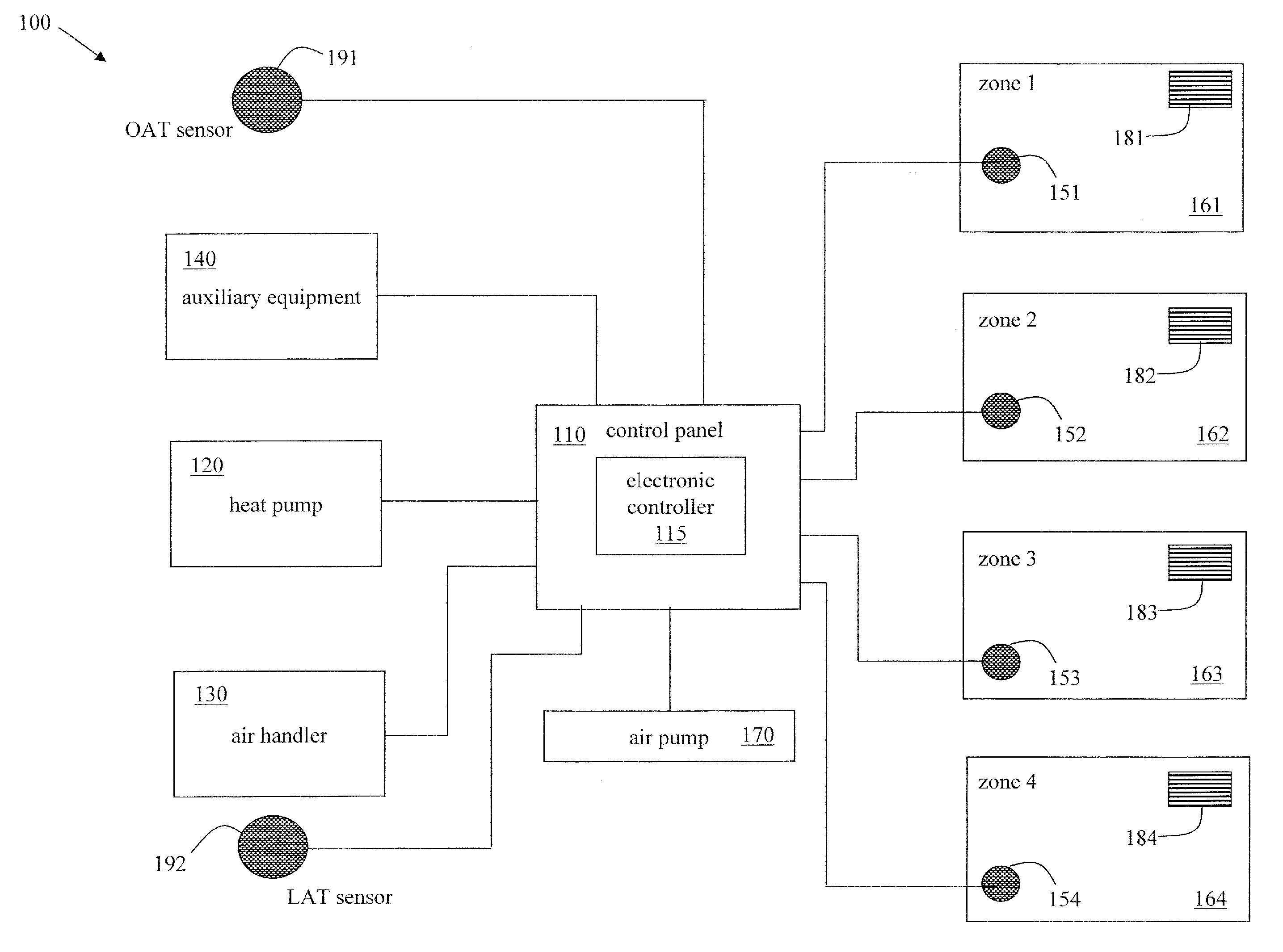
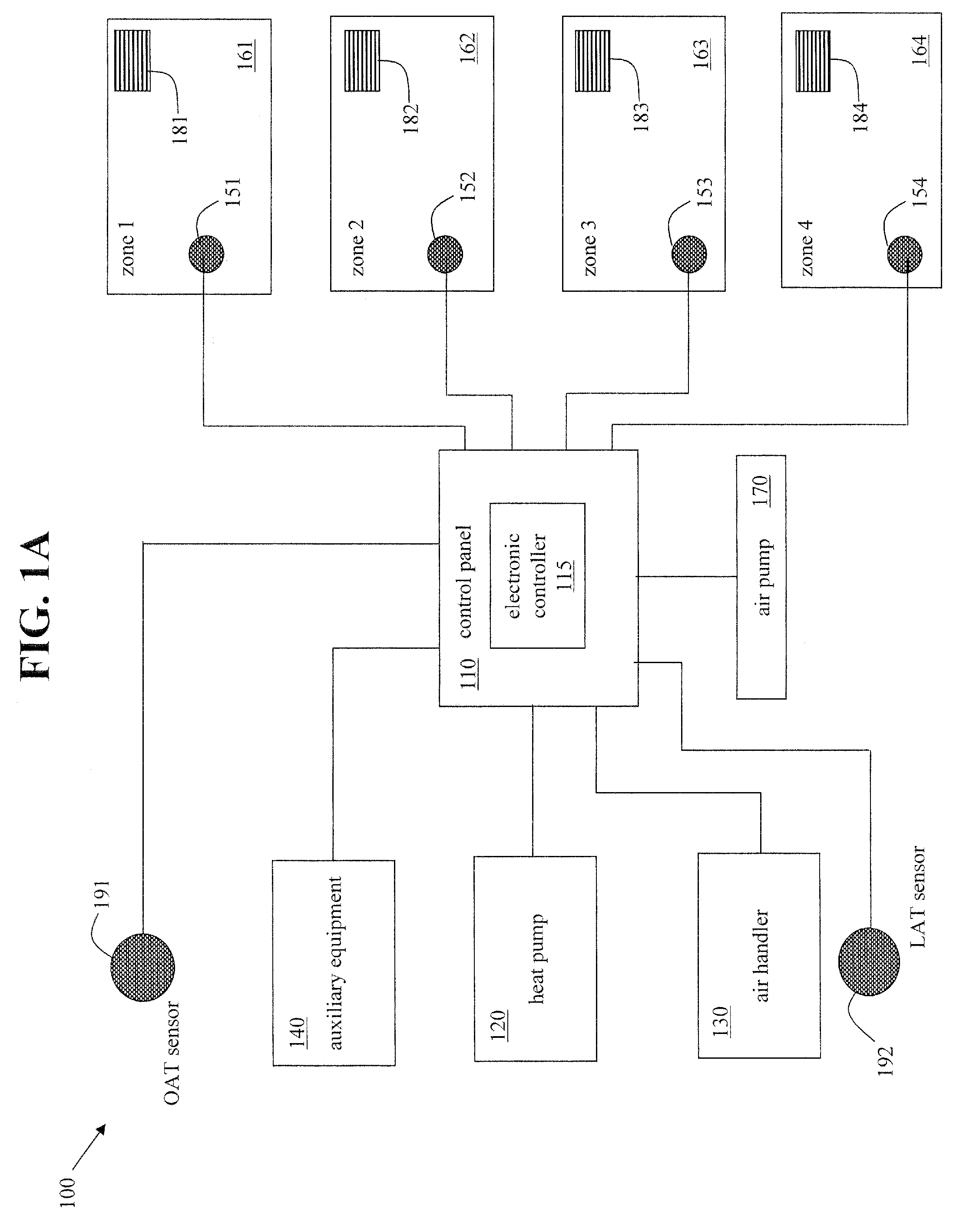
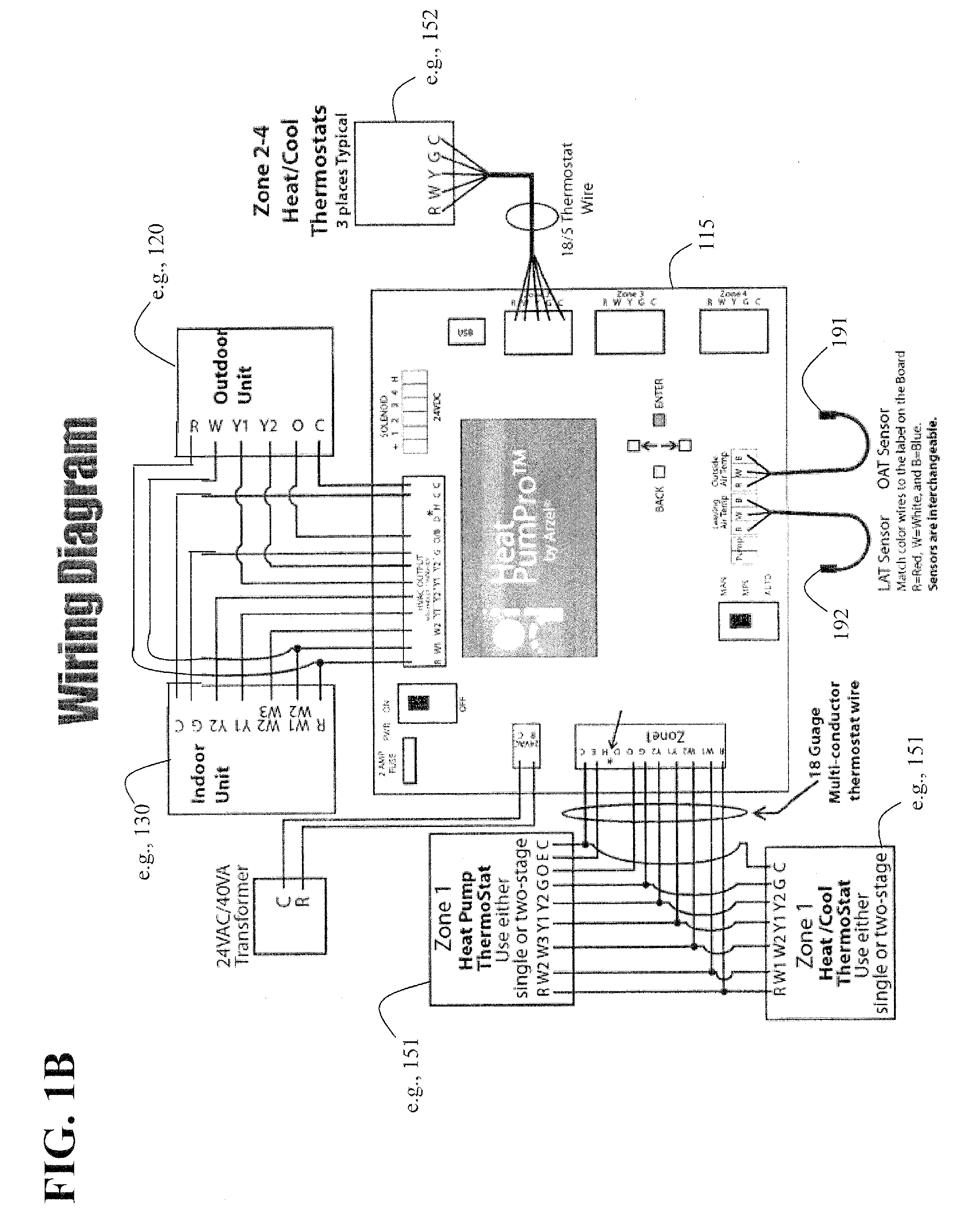
[0079] As used herein, the term “non-proprietary” means useable with any standard commercial forced air system (e.g., any standard commercial heat pump system). FIG. 1A illustrates a schematic block diagram of an exemplary embodiment of a system 100 to control environmental parameters of pre-defined zones within a first environment, in accordance with various aspects of the present invention. The system 100 includes a control panel 110, at the heart of the system 100, which includes an electronic controller 115. The system 100 further includes a heat pump 120 and an air handler 130 both operationally connected to the control panel 110 such that the operation of the heat pump 120 and the air handler 130 may be controlled by the electronic controller 115 of the control panel 110. The system 100 also includes auxiliary equipment 140 operationally connected to the control panel 110 such that the operation of the auxiliary equipment 140 may be controlled by the electronic controller 115 ...


PUM


Abstract

A system and method to control environmental parameters of pre-defined zones within an environment using an electronic controller are disclosed. The system includes a non-proprietary electronic controller which enables a weighting value to be assigned to each zone within the environment. The electronic controller also detects any zone service calls from sensor devices associated with each of the zones and determines a cumulative weighting value in response to the detected zone service calls. The electronic controller selects an equipment staging combination from at least two possible equipment staging combinations in response to thermal capacity, and an air handler stage is selected in response to at least the cumulative zone weighting value.

Description

CROSS-REFERENCE TO RELATED APPLICATIONS / INCORPORATION BY REFERENCE [0001] This U.S. patent application is a continuation-in-part (CIP) of pending U.S. patent application Ser. No. 11 / 226,165, filed on Sep. 14, 2005.TECHNICAL FIELD [0002] Certain embodiments of the present invention relate to zoned control of an environment. More particularly, certain embodiments of the present invention relate to a system and method to control environmental parameters of pre-defined zones within an environment using an electronic controller and weighted zones. BACKGROUND OF THE INVENTION [0003] The cooling and heating of commercial buildings and residential homes is typically accomplished via forced air and forced hot or cooled water distribution systems. A furnace, heat pump, other fossil fuel furnace, and / or air conditioner are typically used to supply heated air or cooled air to areas of the building or home via ducts. Such distribution systems are often controlled by a single thermostat which is ...

Claims


Application Information

Patent Timeline
Patent Type & Authority Applications(United States)
IPC IPC(8): F24F3/00F24D19/10
CPCF24F3/001F24F11/0009F24F11/0012F24F2011/0064F24F2011/0013F24F2011/0061F24F11/0015F24F11/30F24F2110/10F24F2110/12F24F2110/20F24F11/63F24F11/65F24F11/52F24F11/77F24F11/64F24F11/67F24F11/86
Inventor VOTAW, MARKRAMUNNI, JOSEPHDELP, THOMASLAUGHLIN, DENNISZELCZER, ALROTH, LEONARDSIPERSHTEYN, VLADIMIR
Owner ARZEL ZONING TECH
Why Eureka
Try Eureka