Compound tooling system for molding applications

Active Publication Date: 2007-03-22
ODONOGHUE JOSEPH
View PDF31 Cites 106 Cited by
  • Summary
  • Abstract
  • Description
  • Claims
  • Application Information

AI Technical Summary

Benefits of technology

[0033] Mold cavity stability is maintained by the vacuum-bonding of the elastomer skin-mold to the backing-mold. Bonding may be effected in two ways. The perimeter key-way\seal contains apertures or grooves which connect, via a port, within the backing-mold to a vacuum connection molded into the backing-plate. When the grooves or apertures are evacuated, the key of the skin-mold is held tightly in the key-way of the backing-mold and the perimeter sealed. The individual key-ways and general surface of the backing-mold are also similarly grooved and these grooves connect to a second vacuum connection via a second port. As with the perimeter key-way\seal, the backing-mold surface may contain fine apertures

Problems solved by technology

The rigid polymer skin-mold may be mechanically fastened to the b

Method used


Image

  • Compound tooling system for molding applications
  • Compound tooling system for molding applications
  • Compound tooling system for molding applications

Examples


Embodiment Construction

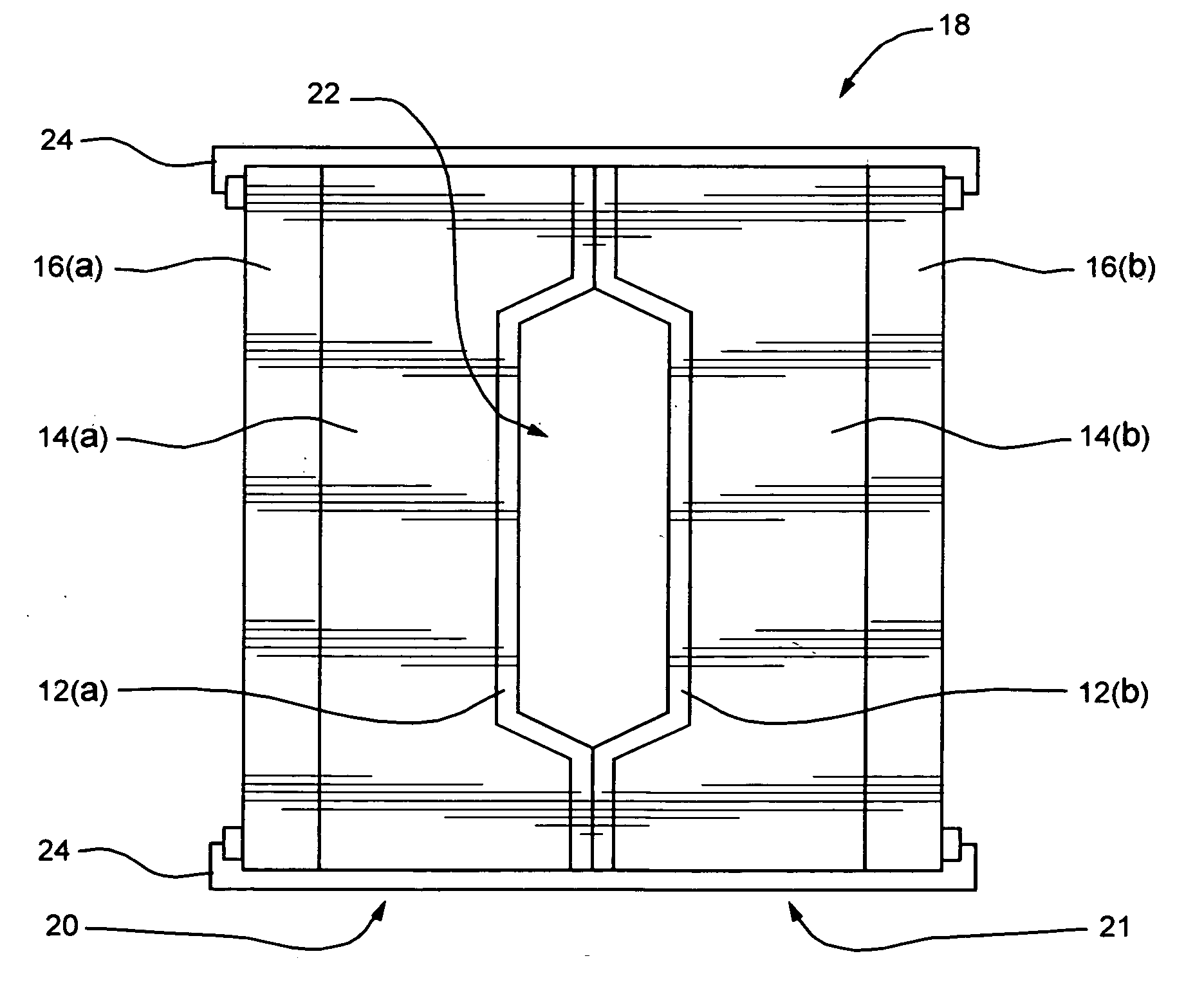
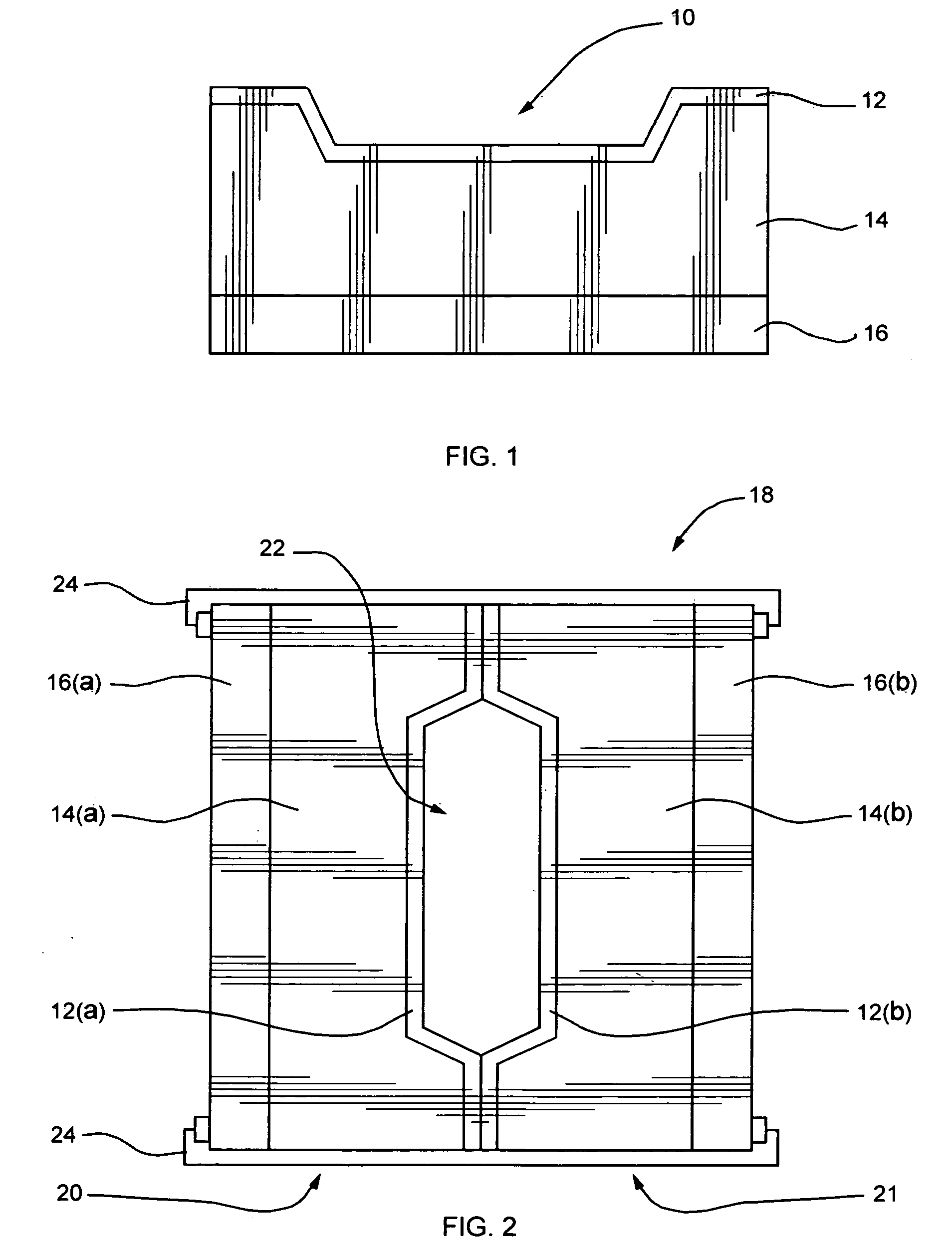
[0045] In a tooling system according to the invention, the standard mold unit, or mold half in the case of matched molds, consists of a three-piece compound mold, the backing-plate, the backing-mold and the skin-mold.

[0046] The backing-plate is preferably one of a standard menu of backing-plates of various sizes and shapes suited to various sizes and shapes of molds depending on the general size and geometry of the part to be molded and carries standard features such as mold clamping systems, process connections, and the like. The backing-plate is designed to be rigid enough to withstand all molding and clamping pressures etc., its design also including whatever is required to integrate the mold into the molding process used, except actual cavity filling systems.

[0047] The backing-mold is a conforming section which mates with the backing-plate according to a standard system of guide pins or keys and is mechanically attached by any suitable means. The backing-mold may be solid, syn...


PUM

PropertyMeasurementUnit
Pressureaaaaaaaaaa
Lengthaaaaaaaaaa
Volumeaaaaaaaaaa

Abstract

A compound mold or tooling system is designed to provide an alternative to conventional, expensive, metal molds for various plastics molding applications. The compound mold comprises a replaceable thin-walled liner, or skin-mold, defining the mold surface, temporarily bonded by vacuum means or mechanical means to a conforming backing-mold mold body supported by a rigid backing-plate. Both skin- and backing-molds are composed of suitable polymers with or without additives, fillers, reinforcements or other inclusions depending on mold requirements. The backing-plate contains standard features and fixtures common to all molds used in the particular process or of a particular geometry.

Description

[0001] This application claims priority from provisional application for patent No. 60 / 717,362 filed on Sep. 16, 2005.FIELD OF THE INVENTION [0002] The invention concerns compound tooling systems for molding applications, and more particularly discloses a compound mold unit for use in plastics molding applications, and methods for using such mold unit. BACKGROUND OF THE INVENTION [0003] Conventional molding methods, particularly methods for injection molding of thermoplastics, generally involve the cycling of a single, usually expensive, hard, permanent mold very rapidly in conjunction with expensive molding equipment. Molds are usually made of steel or other metal alloys and are designed and economical only for large production runs. The high cost of mold production, as well as the high molding pressures used, impose size constraints on the mold and hence the size of the part which can be produced. [0004] Thermosetting liquid resin injection or transfer molding methods generally us...

Claims


Application Information

Patent Timeline
IPC IPC(8): B29C33/40
CPCB29C33/565B29C33/40B33Y80/00
Inventor O'DONOGHUE, JOSEPH
Owner ODONOGHUE JOSEPH
Why Eureka
Try Eureka