
Threaded pipe connector

a technology of threaded pipes and connectors, applied in the direction of hose connections, screw threaded joints, pipe joints, etc., can solve the problems of bending loads and fatigue, failure can be very expensive to repair, and the connection is generally heavy and costly

Inactive Publication Date: 2007-03-22
VETCO GRAY
View PDF13 Cites 28 Cited by
  • Summary
  • Abstract
  • Description
  • Claims
  • Application Information

AI Technical Summary

Benefits of technology

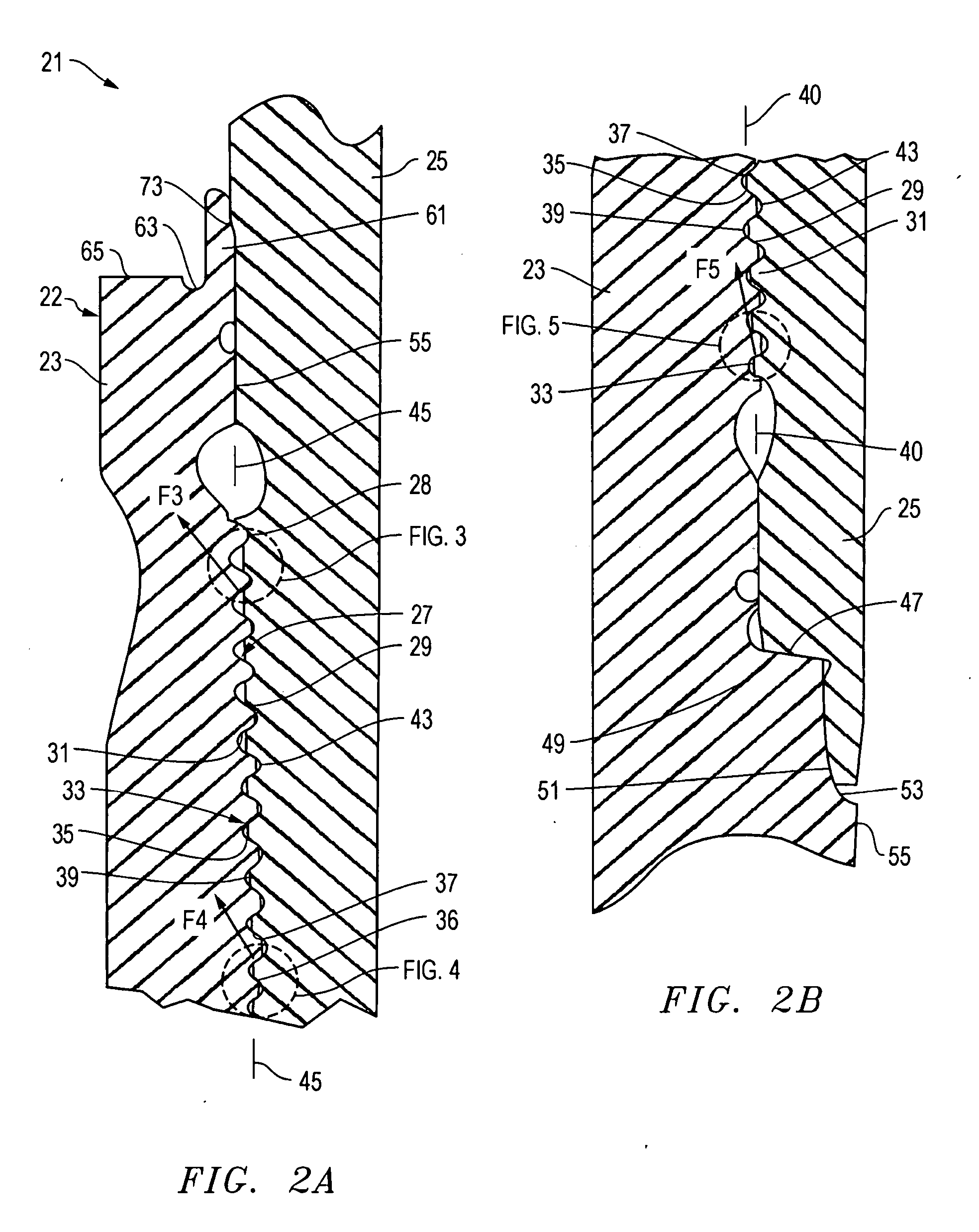
[0010] The connection of the present invention has threadforms in the box and on the pin that have load flanks that engage each other at different points along the length of the threadforms when fully made up. The varying engagement provides a load angle that varies along the length of the threadforms. The load flanks engage each other with varying amounts of interference, or radial distension, along the lengths of the threadforms when fully made up, so that when a tensile load is applied, the resultant sharing of the load throughout the threadforms is fairly uniform. Preferably, the load flanks in the central portion of the threadforms have greater interference when made up than the load flanks in the upper and lower portions. Also, in the preferred embodiment, the stab flanks of some of the threads in the upper portion and the lower portion of the threadforms engage each other with interference when the connector is fully made up.
[0011] In one embodiment, the box has an internal torque shoulder that is engaged with a torque shoulder formed on the pin. An internal metal seal member extends from the pin torque shoulder and engages a recess formed in the bore of the box. The connector may also have an external metal-to-metal seal comprising a seal member that protrudes from the upper end of the box and engages an outer diameter portion of the pin. Preferably, the box seal member has a recessed seal rib that is protected from damage during insertion of the pin into the box.

Problems solved by technology

These risers are subject to tensile loads, bending loads and fatigue due to current and waves.
These risers may be in place for years, and a failure can be very expensive to repair.
For the welded-on connection type, the connection is generally heavy and costly.
It also must be welded onto the main pipe body, and therefore becomes limited by the weld itself.
In addition, the fatigue life of the weld is substantially inferior, in most cases, to that of the connection itself.
Therefore this type of connection is limited in both structural and fatigue strength by the pipe weld.
For the threaded and coupled connection, since the entire connection must be formed on the limited cross-section of the pipe, there are significant limits on what can be utilized for the same features that allow weld-on connectors to achieve high levels of performance.
While connections of this type typically only have slightly limited structural strength, they have significantly reduced fatigue strength.
They are also somewhat compromised in the ability to achieve reliable metal-to-metal seals external to the threaded section as well as achieve an effective stab guide in this same location.

Method used


Image

  • Threaded pipe connector
  • Threaded pipe connector
  • Threaded pipe connector

Examples


Embodiment Construction

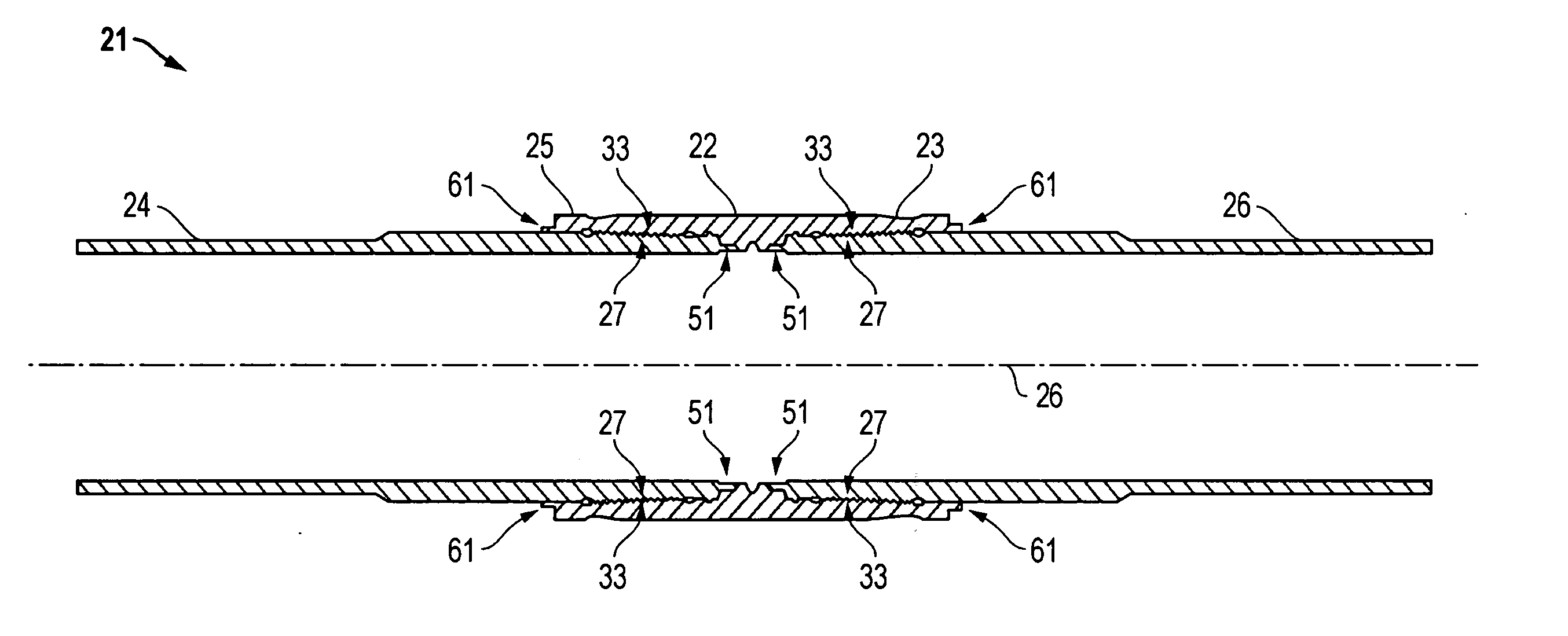
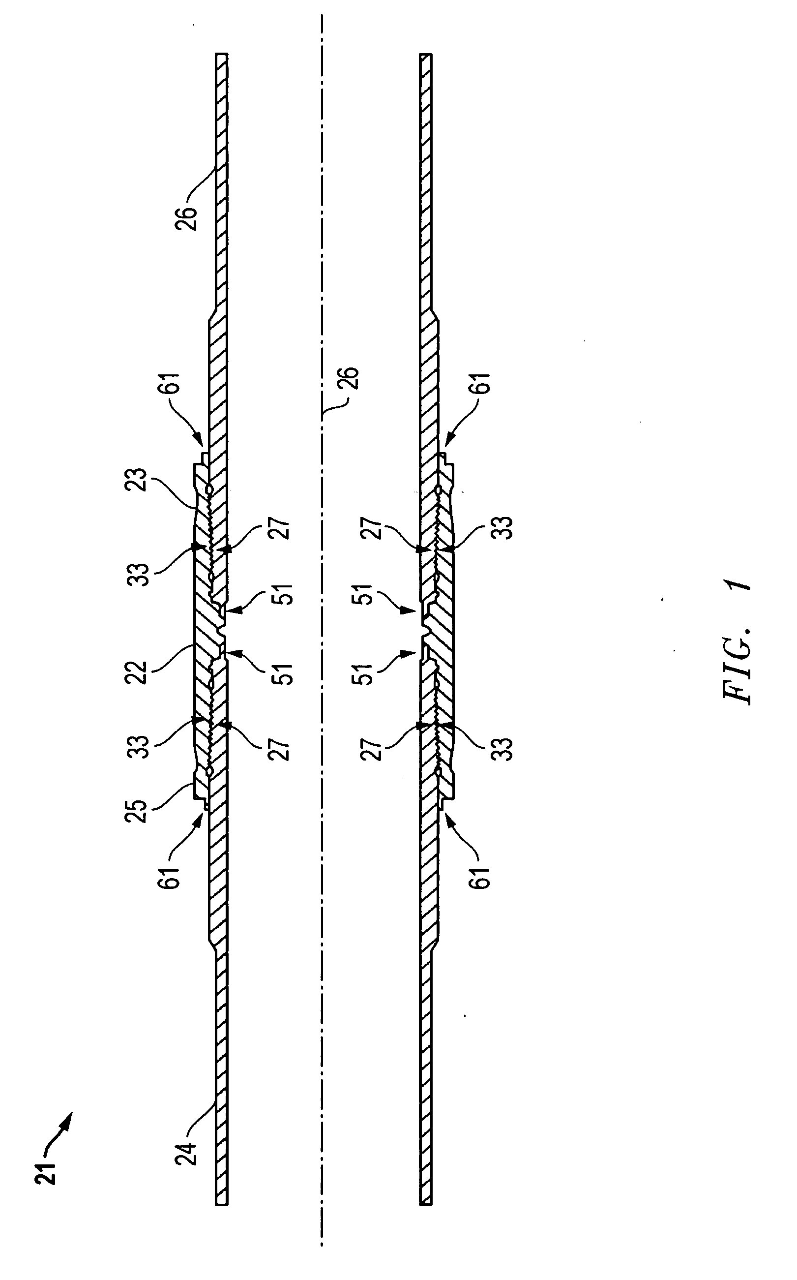
[0026] Referring to FIGS. 1-9, one embodiment of a pipe connector in accordance with this invention is illustrated as a threaded connection 21. Connection 21 may be used for a variety of purposes, but is particularly suitable for subsea oil and gas production with top tension and catenary risers. In this example, connection 21 comprises a coupling sleeve 22 having two box or female members 23, each for engaging a pin or male member 25. In this embodiment, pin 25 is shown integrally formed on an upset or enlarged ends of a pipe 24. The boxes 23 of coupling sleeve 22 join two pins 25 of two pipes 24. For some applications, each pipe 24 could have a pin 25 welded to or formed on one end and a box 23 welded to or formed on the opposite end. Pin 25 and box 23 have a common longitudinal axis 26 when connected.

[0027] Referring to FIGS. 2A and 2B, box 23 has an internal threadform 27 (FIG. 2A, 2B) that is tapered, having a larger inner diameter at toward its rim or upper end and a smaller ...


PUM


Abstract

A riser connector uses a box and upset pin connector threadform design having S-shaped load flanks that provide a variable load angles depending on the radial position along the engaged teeth. This design promotes a load path that changes with position along the axial length of the engaged thread, as well as increasing or decreasing external loads on the connector. The connector also varies radial distention of the pin from the box in a manner that is different from one thread to the next. The threadform uses a combination of thread cuts that vary in shape, pitch, and / or thread cone angle to provide load and stab flanks, as well as a load path, that vary from one axial end of the engaged thread to the other.

Description

BACKGROUND OF THE INVENTION [0001] 1. Technical Field [0002] The present invention relates in general to threaded pipe connectors and, in particular, to a pipe connector designed for high fatigue such as offshore well riser connections. [0003] 2. Description of the Related Art [0004] In some types of offshore oil and gas production, risers extend from the sea floor to a floating platform for processing and transferring the well fluid to a pipe line. Production risers may be thousands of feet in length and may extend in a long catenary curve from the platform to the subsea well assembly. These risers are subject to tensile loads, bending loads and fatigue due to current and waves. These risers may be in place for years, and a failure can be very expensive to repair. [0005] Generally, there are two types of production riser connections that have been used to produce oil and gas from a subsea wellhead to a surface production tree on a floating offshore platform. Both types utilize a fe...

Claims


Application Information

Patent Timeline
IPC IPC(8): F16L15/00
CPCF16L15/004F16L15/06
Inventor PALLINI, JOSEPH W. JR.MUNK, BRIAN N.RIHA, JESSE B.LYLE, ROCKFORD D.
Owner VETCO GRAY
Learn More