Dynamic-quantity sensor

a dynamic-quantity sensor and sensor technology, applied in the direction of generator/motor, acceleration measurement using interia force, instruments, etc., can solve the problems of difficult to reduce the size and cost of such a dynamic-quantity sensor, so as to improve the circuit configuration and reduce the size and cost

Active Publication Date: 2007-03-22
MURATA MFG CO LTD
View PDF9 Cites 9 Cited by
  • Summary
  • Abstract
  • Description
  • Claims
  • Application Information

AI Technical Summary

Benefits of technology

[0008] To overcome the problems described above, preferred embodiments of the present invention provide a dynamic-quantity sensor whose...

Problems solved by technology

It is thus difficult to reduce the size and cost of such an acceleration sensor.
Similarly, the dynamic-quantity sensor in Patent Document 2 requires relatively large-scale circuits, such as the current-to-voltage-converting/s...

Method used


Image

  • Dynamic-quantity sensor
  • Dynamic-quantity sensor
  • Dynamic-quantity sensor

Examples


Embodiment Construction

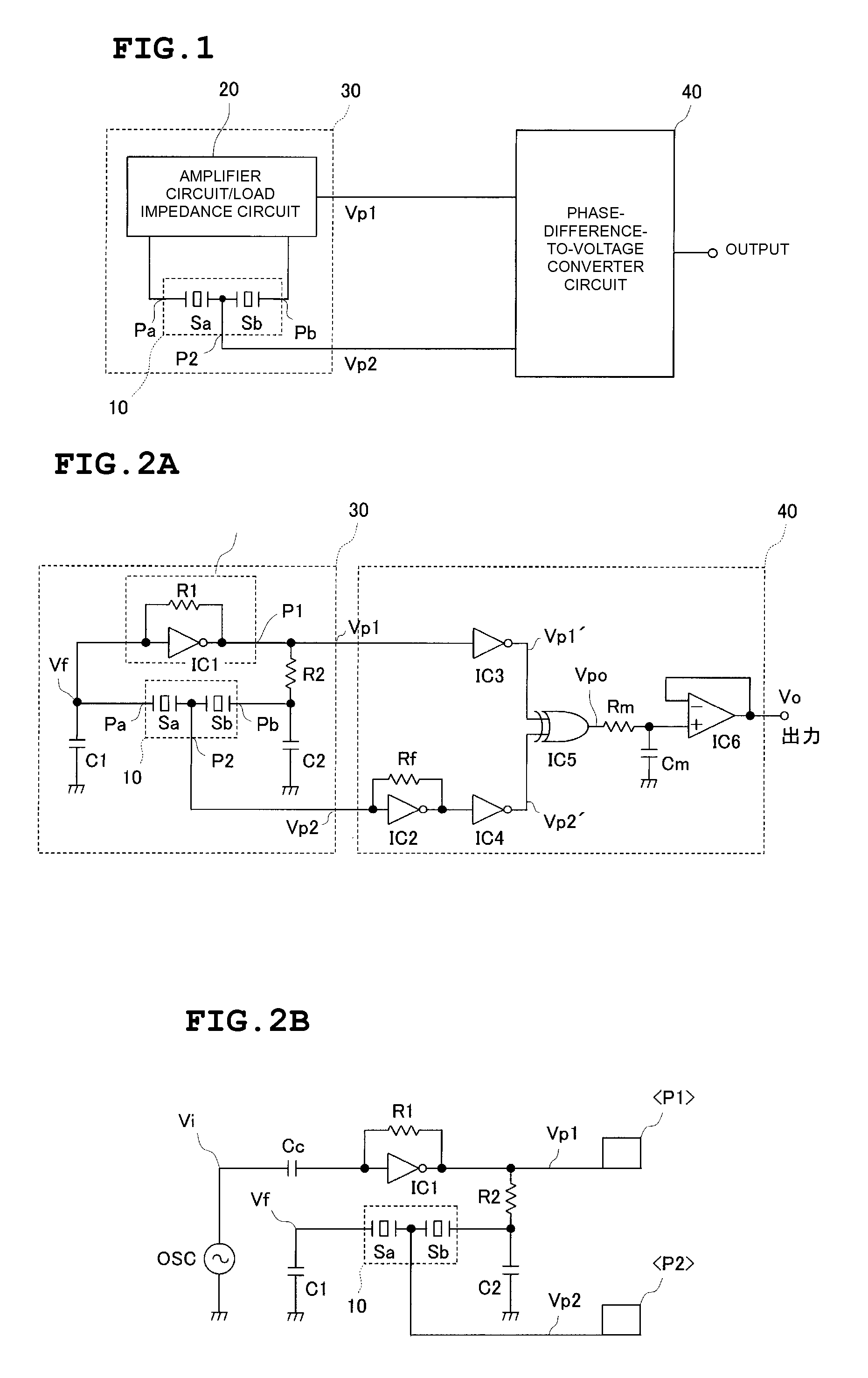
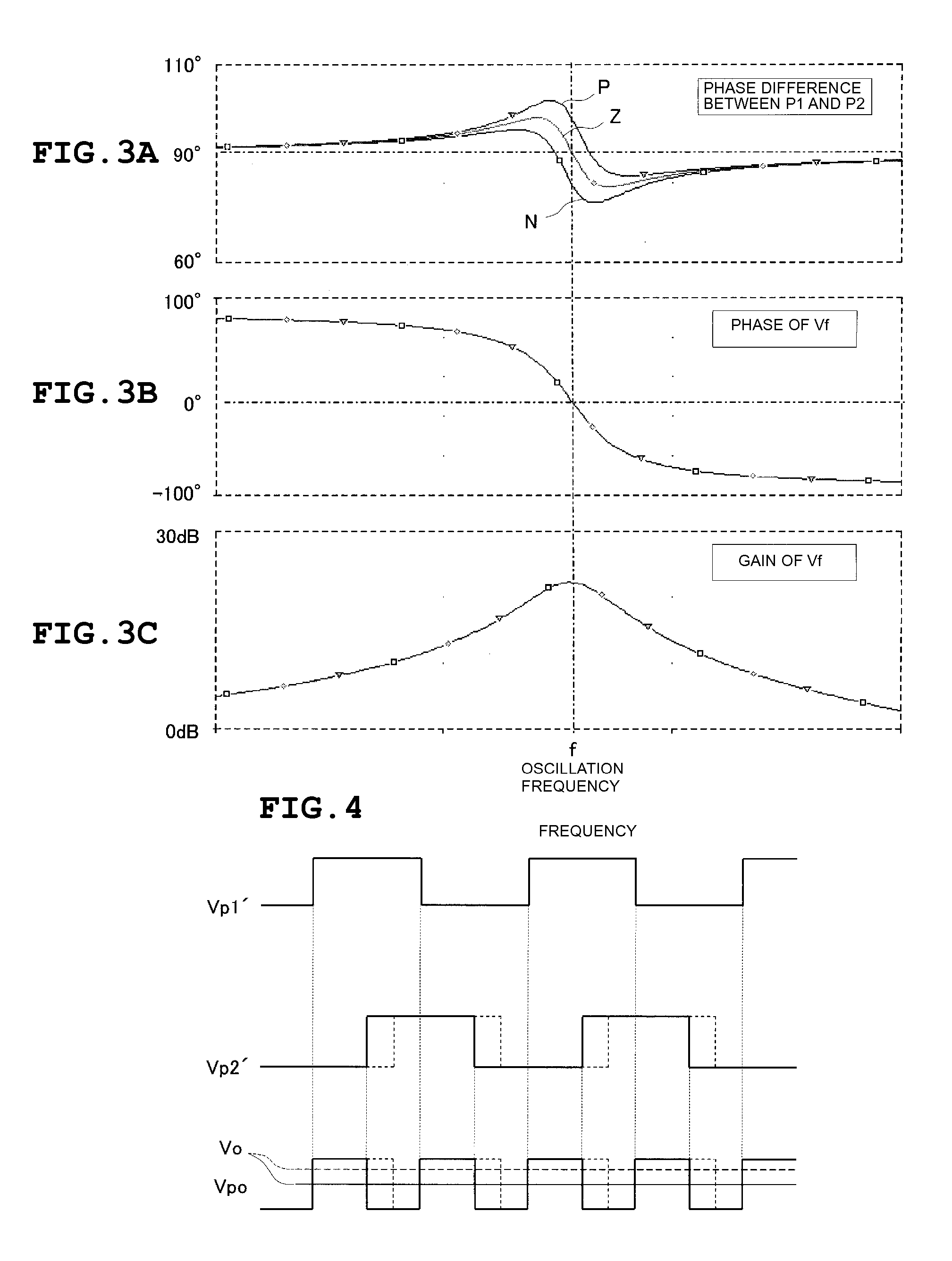
[0032] With reference to FIGS. 1 to 4 and 10 to 12, the configuration of a dynamic-quantity sensor according to a first preferred embodiment will be described.

[0033]FIG. 1 is a block diagram of a dynamic-quantity sensor. Two piezoelectric vibrators Sa and Sb are disposed so that stresses induced by a dynamic quantity are applied thereto in opposite directions. These two piezoelectric vibrators Sa and Sb are connected in series to define a piezoelectric-vibrator series circuit 10. The piezoelectric-vibrator series circuit 10 and an amplifier circuit / load impedance circuit 20 define a Colpitts oscillator circuit 30. A phase-difference-to-voltage converter circuit 40 detects a voltage phase difference between voltages Vp1 and Vp2 output from the oscillator circuit 30 as a voltage signal, which serves as an output signal of the dynamic-quantity sensor.

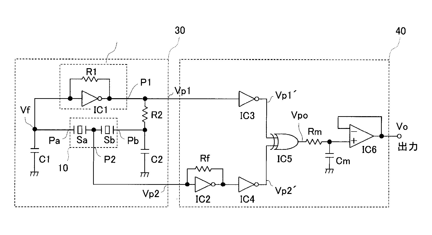
[0034]FIGS. 2A and 2B include specific circuit diagrams of the dynamic-quantity sensor shown in FIG. 1. In the oscillator circuit 30, a...


PUM


Abstract

A piezoelectric-vibrator series circuit including two series-connected piezoelectric vibrators to which stresses induced by a dynamic quantity are applied in opposite directions is used, and a Colpitts oscillator circuit is defined by the piezoelectric-vibrator series circuit and an amplifier circuit/load impedance circuit. A phase-difference-to-voltage converter circuit is provided to convert a phase difference between an output voltage of the oscillator circuit and a voltage at a piezoelectric-vibrator series node of the piezoelectric-vibrator series circuit into a voltage signal.

Description

BACKGROUND OF THE INVENTION [0001] 1. Field of the Invention [0002] The present invention relates to a dynamic-quantity sensor for sensing a dynamic quantity, such as acceleration, angular acceleration, angular velocity, or load. [0003] 2. Description of the Related Art [0004] The present applicant has filed Japanese Unexamined Patent Application Publication 2002-243757 (Patent Document 1) and Japanese Unexamined Patent Application Publication 2003-254991 (Patent Document 2) regarding a dynamic-quantity sensor with piezoelectric vibrators. [0005] The configuration of an acceleration sensor in Patent Document 1 is shown in FIG. 13 herein. As shown in FIG. 13, a bridge circuit 110 includes two piezoelectric vibrators S1 and S2 to which stresses induced by acceleration are applied in opposite directions, and capacitors C1 and C2. A voltage-dividing impedance circuit 120 is disposed between nodes p2 and p3. A signal at a voltage division point p5 of the voltage-dividing impedance circui...

Claims


Application Information

Patent Timeline
IPC IPC(8): H01L41/00G01L1/16G01P15/09G01P15/10
CPCG01P15/09G01L1/162
Inventor YAMASHITA, MUNEHARU
Owner MURATA MFG CO LTD
Why Eureka
Try Eureka