Volume circuit using resistive ladder circuits

a resistive ladder circuit and volume circuit technology, applied in the direction of gain control, transducer casing/cabinet/support, electrical transducer, etc., can solve the problem of difficulty in accurately and sufficiently narrowing down the gain of an input signal in a conventional electronic volume circuit, and achieve high resolution, control and narrow down the gain of an input signal. , the effect of improving circuit configuration

Inactive Publication Date: 2007-11-20
YAMAHA CORP
View PDF14 Cites 8 Cited by
  • Summary
  • Abstract
  • Description
  • Claims
  • Application Information

AI Technical Summary

Benefits of technology

[0006]It is an object of the invention to provide a volume circuit having a high resolution in controlling and narrowing down the gain of an input signal by introducing various improvements in circuit configurations. That is, the volume circuit uses a resistive voltage divider circuit, which can provide a desired tap voltage in a high resolution. In addition, a resistive current control circuit coupled with the resistive voltage divider circuit is designed to eliminate unwanted influences on the output line resistance of the resistive voltage divider circuit.

Problems solved by technology

Therefore, it is difficult to accurately and sufficiently narrow down the gain of an input signal in a conventional electronic volume circuit.

Method used


Image

  • Volume circuit using resistive ladder circuits
  • Volume circuit using resistive ladder circuits
  • Volume circuit using resistive ladder circuits

Examples


first embodiment

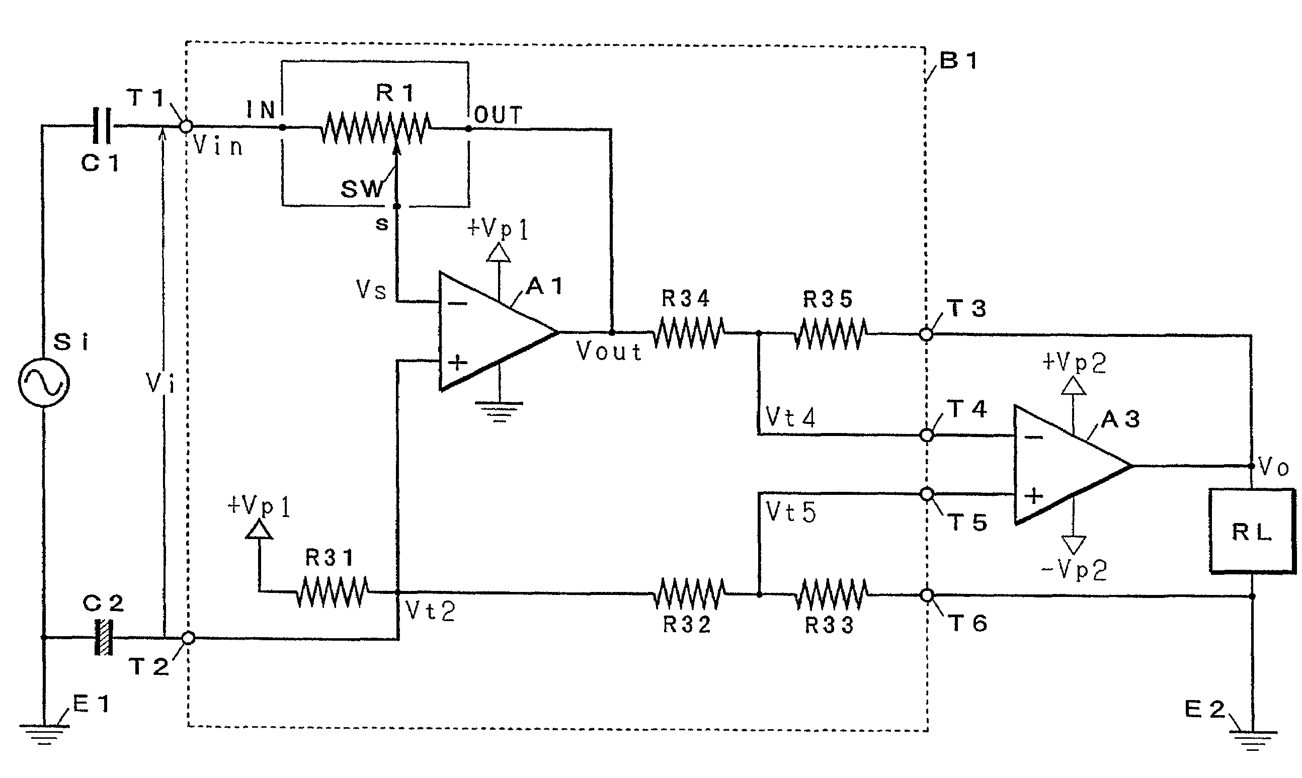
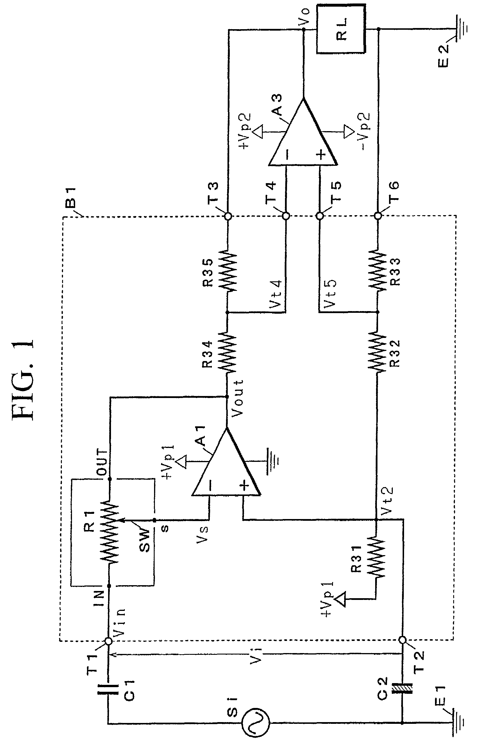
[0033]FIG. 1 shows the overall configuration of an electronic volume circuit in accordance with the first embodiment of the invention. The volume circuit of FIG. 1 contains an LSI circuit ‘B1’ (encompassed by dotted lines), which provides a voltage divider realized by resistive ladder circuits R1, a switch circuit SW, an inversion-type operation amplifier A1 that operates by a single source voltage +Vp1, a series of resistors R31, R32, and R33 that are connected in series with a constant voltage source in order to gain a reference potential, and a series of resistors R34 and R35 that are used to output signals.

[0034]The LSI circuit B1 has two input terminals T1 and T2, and four output terminals T3 to T6. A capacitor C1 for cutting out dc current flowing therethrough is connected to the input terminal T1; and a capacitor C2 for stabilizing the input of the LSI circuit B1 is connected to the input terminal T2. Hence, an input signal source Si is connected between the input terminals T...

second embodiment

[0090]FIG. 9 shows the overall configuration of an electronic volume circuit in accordance with a second embodiment of the invention, wherein parts and components identical to those shown in FIG. 1 will be designated by the same reference symbols and numerals. The electronic volume circuit of the second embodiment shown in FIG. 9 provides an LSI circuit B2 that contains secondary resistive ladder circuits R2 and a secondary inversion-type operational amplifier A2, which operates by the source voltage +Vp1, in addition to the resistive ladder circuits R1 and the operation amplifier A1. Due to the provision of the secondary resistive ladder circuits R2 and the secondary operation amplifier A2, the LSI circuit B2 additionally provides current control functions and wiring resistance cancellation functions compared with the LSI circuit B1 shown in FIG. 1. FIG. 9 merely shows an equivalent circuit for representation of series connections between the resistive ladder circuits R1 and R2. Th...


PUM


Abstract

A volume circuit contains resistive ladder circuits, from which a desired fractional voltage output (Vs) is extracted and supplied to an amplifier to provide an output voltage (Vout). The resistive ladder circuits comprise multiple lines of series resistances, wherein each line contains a resistance portion ‘nR’ (where ‘n’ denotes a division index, and ‘R’ denotes an element resistance) that is connected in parallel with a next line, so that an overall resistance of following lines is ‘(n−1)×n’ times larger than the element resistance. Secondary resistive ladder circuits can be additionally arranged in series in order to control a secondary amplifier that absorbs excessive currents flowing into the resistive ladder circuits. The secondary resistive ladder circuits are constituted symmetrically with the resistive ladder circuits, in which output terminals (t1-t12) are all set to the same potential.

Description

BACKGROUND OF THE INVENTION[0001]1. Field of the Invention[0002]This invention relates to volume circuits that use resistive ladder circuits for adjustments of audio signals in volume levels.[0003]2. Description of the Related Art[0004]In the fields of audio devices and technologies, electronic volume circuits for fabricating electronic circuits are conventionally used for adjustments of volumes in audio signals. Japanese patent application No. 2000-28152 (i.e., Japanese Unexamined Patent Publication No. 2001-217660; and U.S. patent application Ser. No. 09 / 773,646) disclosed an example of an electronic volume circuit that is driven by a single power source and whose components are fabricated together as LSI circuitry.[0005]In the aforementioned electronic volume circuit, the gain (or attenuation) of an input signal is controlled by selecting a tap (or a voltage division point) from series resistance. In particular, when the gain is greatly narrowed down, resistance division points s...

Claims


Application Information

Patent Timeline
Patent Type & Authority Patents(United States)
IPC IPC(8): H03G3/00H01C13/02H03F3/45H03G1/00H03G3/12
CPCH03F3/45475H03G1/0088H03F2203/45591H03G3/00
Inventor TSUJI, NOBUAKIUCHIDA, HISATOSHI
Owner YAMAHA CORP
Why Eureka
Try Eureka