Compact fluorescent lamp and method for manufacturing

a fluorescent lamp and compact technology, applied in the manufacture of electrode systems, cold cathode manufacturing, electric discharge tube/lamp manufacture, etc., can solve the problems of large length dimension, low manufacturing efficiency, and low efficiency of fluorescent lamps, so as to improve the resistance to mechanical vibration and simplify the sequential manufacturing steps

Inactive Publication Date: 2007-03-22
GENERAL ELECTRIC CO
View PDF13 Cites 52 Cited by
  • Summary
  • Abstract
  • Description
  • Claims
  • Application Information

AI Technical Summary

Benefits of technology

[0008] The disclosed compact fluorescent lamps ensure that the available lamp is well protected against any intrusion of dust and humidity from the outside atmosphere into the inside volume of the outer envelope. The position of the printed circuit board carrying the ballast circuit is selected as low as possible in proximity of the sealing means and the separating line is at a distance above the plane of the printed circuit board sufficient to provide appropriate thermal protection during reconnecting and sealing the two parts by welding. The geometry of the outer envelope and the selection of the position of the circumferential separation line between the upper and the lower part of the outer envelope enable the use of short and rigid power supply lead-out wires between the ballast circuit and base contact terminals, which eliminates the need for any isolation. Using the printed circuit board as suggested above, the consecutive manufacturing steps may be simplified, thereby providing better conditions for a mass production. By providing fixing means for fixing the position of the discharge tubes inside the outer envelope, a compact fluorescent lamp is made available which is more resistant to mechanical vibrations and shocks.

Problems solved by technology

Disadvantageous is however their relatively high price and large length dimension.
Most of these constructions however lack any means for protecting the lamp against adverse environmental effects.
In case of any damage to the outer envelope, the arc generating and sustaining medium containing mercury is set free, which is harmful to the environment.
Although this lamp is less harmful to the environment in case of damage of the outer envelope, difficulties may arise during production due to the use of the heat shield disposed between the lamp and the ballast.
The manufacturing steps of mounting the ballast circuit board on the discharge tube and connecting the electrodes of the discharge tube to the ballast circuit appear to be in conflict with each other.
On the other side, if the electrodes of the discharge tube are already connected to the ballast circuit, the insertion of the ballast circuit board is no more possible.
A further shortcoming of this lamp is that the outer envelope is not sealed hermetically and therefore the discharge tube arrangement is not protected against adverse influence of the atmosphere.

Method used


Image

  • Compact fluorescent lamp and method for manufacturing
  • Compact fluorescent lamp and method for manufacturing
  • Compact fluorescent lamp and method for manufacturing

Examples


Embodiment Construction

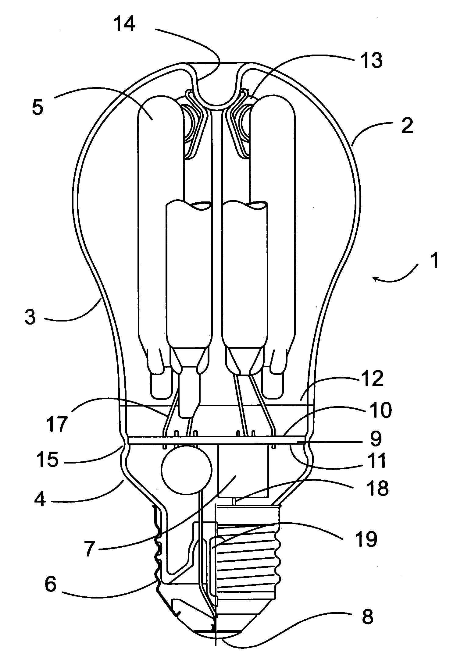
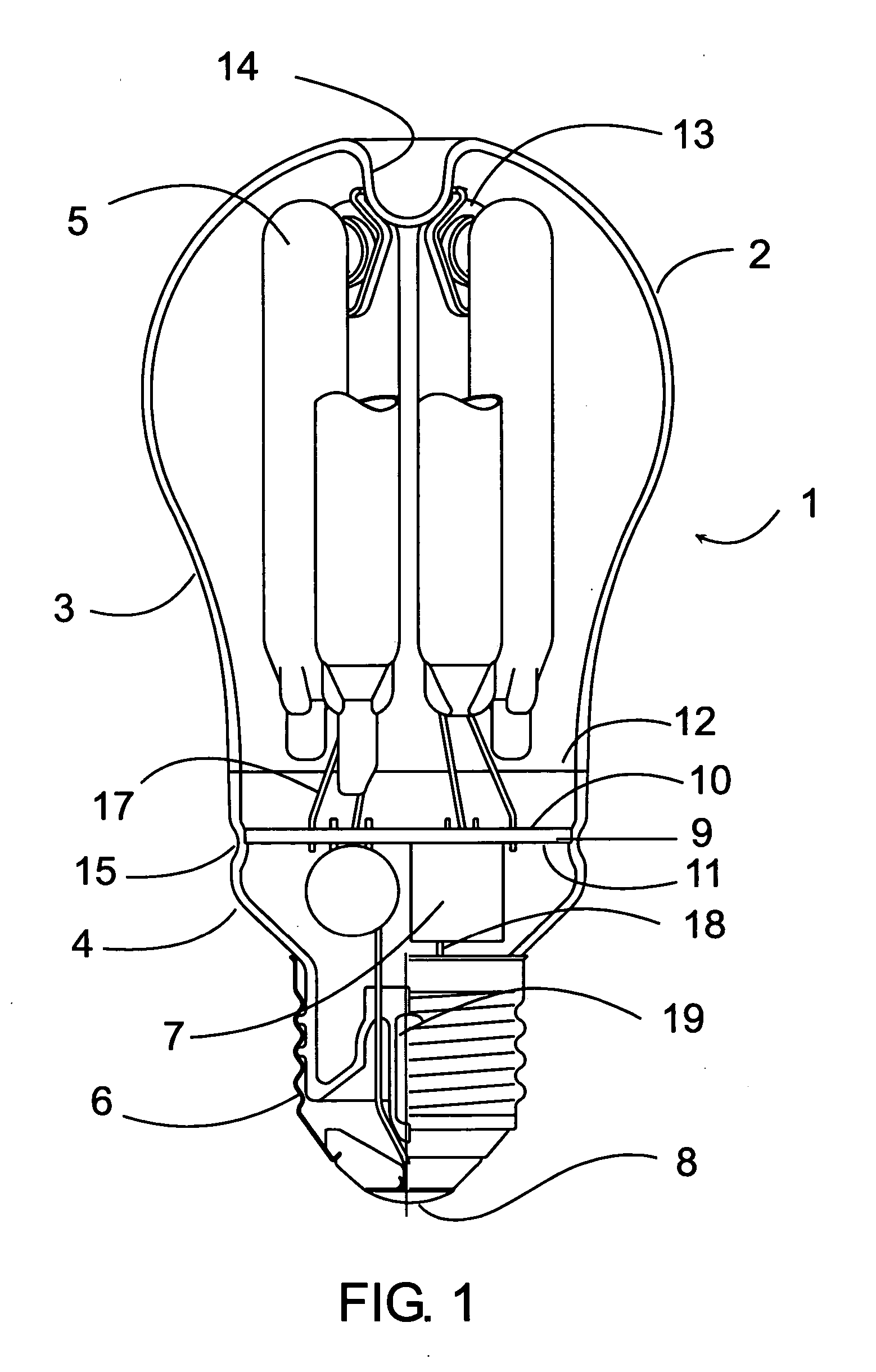
[0021] Referring now to FIG. 1, a low-pressure discharge lamp I is shown. The lamp is a fluorescent discharge lamp, with an outer envelope 2 enclosing a discharge tube arrangement 5 and a ballast circuit 7. The outer envelope 2 may be transparent or translucent, and may be made of glass. The outer envelope 2 has a substantially spherical portion and an elongated end portion. The outer envelope 2 is hermetically sealed at its elongated end portion and connected to a base 6. The outer envelope is cut in two parts and separated at cutting line 12 in order that the ballast circuit 7 and the discharge tube arrangement 5 can be inserted and connected inside the outer envelope 2 as described in detail below. The discharge tube arrangement 5 comprises a plurality of elongated discharge tubes. The discharge tubes are made of glass, and enclose a discharge volume filled with a discharge gas, and have a fluorescent phosphor coating disposed on the inner surface of the tubes. The ends of the tu...


PUM


Abstract

This compact fluorescent lamp comprises a discharge tube arrangement with at least one discharge tube. The tube is formed of glass, encloses a discharge volume filled with a discharge gas and has a fluorescent phosphor coating disposed on the inner surface of the tube. The tube forms a continuous arc path and the tube is provided with electrodes disposed at each end of the arc path. The lamp also comprises a ballast circuit connected to the electrodes for controlling the current in the tube and a lamp base for connecting said lamp to a power supply through a socket. The lamp is enclosed in an outer envelope comprising a substantially spherical portion enclosing the tube arrangement and an elongated end portion enclosing the ballast circuit. The end portion of the outer envelope is closed and sealed by a sealing means of the same material as the material of the outer envelope. The sealing means is connected to the envelope in a hermetically sealing way. A method for manufacturing a compact fluorescent lamp as described above is also disclosed. In the method, an outer envelope with an open end on the base side is provided. The open end of the envelope is closed and sealed with a sealing means to provide a hermetic seal. The envelope is separated by cutting along a circumferential line into an upper part and a lower part. The ballast circuit is introduced into the lower part and respective connection points of the ballast circuit are connected to power supply lead-out wires. The discharge tube arrangement is connected to respective connection points of the ballast circuit by lead-in wires. The lead-in wires and the lead-out wires are short and need not be insulated. The ballast circuit and the discharge tube arrangement are held and supported in the outer envelope by the connecting wires and fixing means.

Description

FIELD OF THE INVENTION [0001] This invention relates to compact fluorescent lamps, and more particularly to compact fluorescent lamps primarily for outdoor use. Even more specifically this invention relates to low-pressure compact fluorescent lamps, which can be used under extreme circumstances. BACKGROUND OF THE INVENTION [0002] The majority of known and commercially available low-pressure discharge lamps are so-called compact fluorescent lamps. These lamps are determined to replace incandescent lamps used in a wide field of industry and home applications. Main advantages of these lamps are the relatively low power consumption and a long lifetime. Disadvantageous is however their relatively high price and large length dimension. Many configurations have been proposed to solve the length dimension problem. Such solutions include the multiple tube arrangements and the coiled tube arrangements. Most of these constructions however lack any means for protecting the lamp against adverse ...

Claims


Application Information

Patent Timeline
Patent Type & Authority Applications(United States)
IPC IPC(8): H01J61/30
CPCH01J5/62H01J9/266H01J9/34Y02B20/19H01J61/327H01J61/34H01J9/36Y02B20/00
Inventor WURSCHING, ISTVANBANKUTI, LASZLOPAPP, FERENCFULOP, JOZSEF
Owner GENERAL ELECTRIC CO
Why Eureka
Try Eureka