Switched mode power converter

Active Publication Date: 2007-03-22
SKYWORKS SOLUTIONS INC
View PDF28 Cites 35 Cited by
  • Summary
  • Abstract
  • Description
  • Claims
  • Application Information

AI Technical Summary

Benefits of technology

[0011] To overcome the drawbacks of the prior art and provide additional benefits as would be understood by one of ordinary skill in the art, a multi-mode voltage converter is disclosed. To achieve operation of the voltage converter over multiple modes, such as continuous conduction mode and discontinuous conduction mode, the voltage converter monitors opera

Problems solved by technology

In addition, these issues apply to all electronic devices, not just battery operated or portable electronic devices.
As can be appreciated, this system and method for voltage conversion is inefficient due to current consumption by the resistor 108 which is wasted as heat energy.
This reduces power consumption but undesirably creates other problems that arise when the load voltage requirements vary.
A further

Method used


Image

  • Switched mode power converter
  • Switched mode power converter
  • Switched mode power converter

Examples


Example

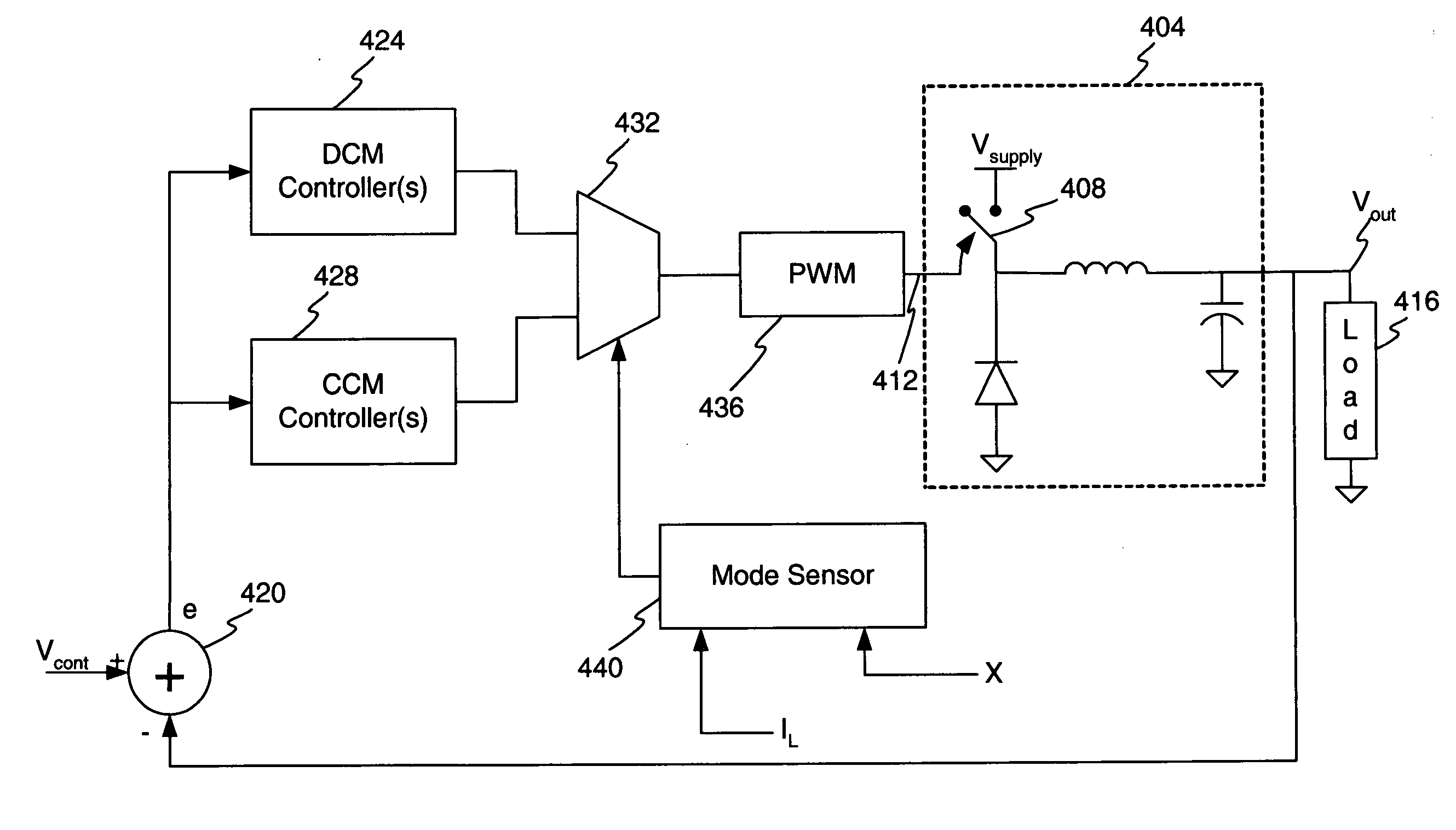
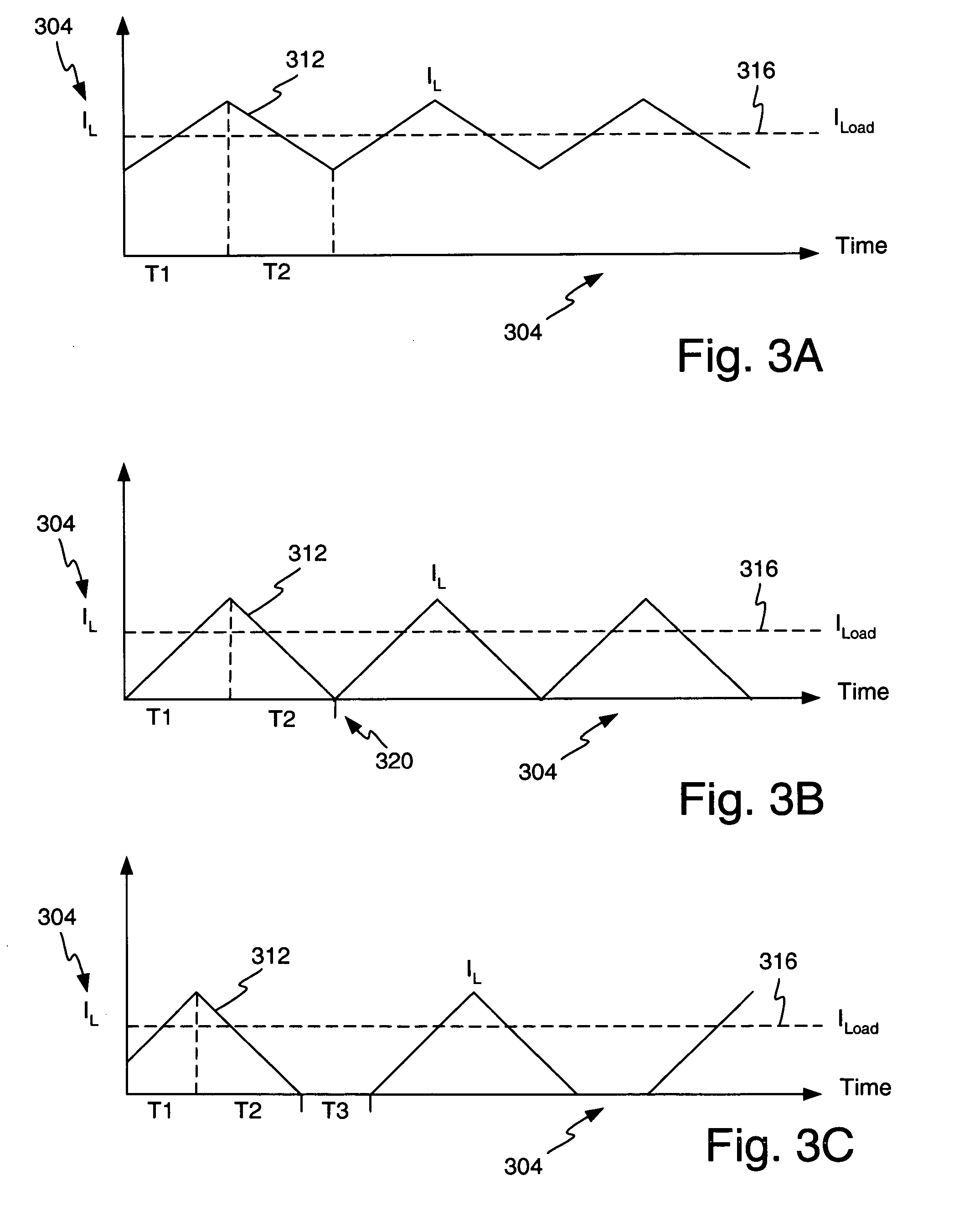
[0031] To overcome the drawbacks of the prior art and provide a more efficient, stable, and accurate voltage converter, a multi-mode voltage converter is disclosed. To gain an understanding of the benefits provided by a multi-mode voltage converter, the various modes of operation are shown in FIG. 3. The plots of FIG. 3 illustrate continuous conduction mode CCM (FIG. 3A), critical conduction mode or boundary mode (FIG. 3B), and discontinuous conduction mode DCM (FIG. 3C). In all of plots of FIG. 3, the horizontal axis 304 represents time, while the vertical axis 308 represents the magnitude of IL 312. In certain figures, a plot of ILOAD 316 is also shown. Each figure is discussed below.

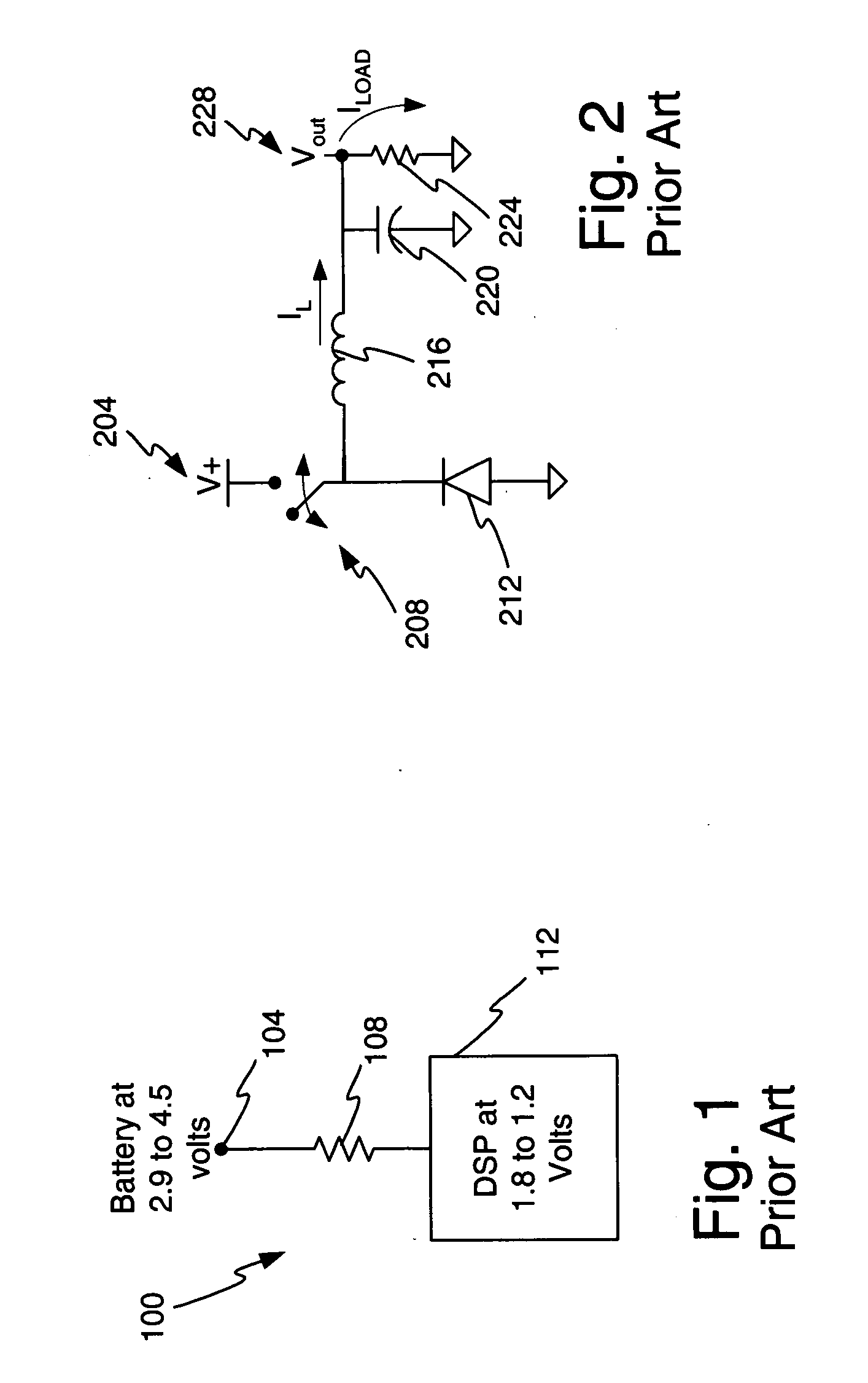
[0032] In general, prior art power converters, such at that shown in FIG. 2 were designed to operate in DCM or CCM. When a prior art power converter transitioned into different modes of operation, it risked entering an unstable state of operation or becoming an un-optimized converter, such as lacking...


PUM


Abstract

A voltage converter having a controller capable of maintaining stable operation of a voltage converter over multiple modes of operation. The voltage converter provides a feedback signal to an error signal generator. One or more controllers, which are selectively established as part of the feedback loop, process the error signal to generate a voltage converter charging cycle control signal. A pulse width modulator may be utilized to generate a voltage converter switch control signal that controls the charge cycle. A detector or comparator monitors one or more aspects of operation of the control circuit or the voltage converter to detect changes in the mode of operation. Upon detection of a change, the detector or comparator generate a multi-mode control signal to selectively switch one or more sub-controllers into or out of the feedback loop to thereby maintain desired stability, loop bandwidth, and response time.

Description

1. FIELD OF THE INVENTION [0001] The invention relates to voltage regulation and in particular to a method and apparatus for multi-mode voltage regulation. 2. RELATED ART [0002] The electronic devices, circuits, and sub-systems with an electronic device may require different voltage to achieve desired operation. For example, within a portable electronic device, such as a mobile telephone or a music player, the analog systems may require a different supply voltage than the digital systems. By way of example, the analog power amplifier may require a 3.2 volt supply voltage while a digital portion of the device may only require 1.8 volts. [0003] To maintain battery efficiency and insure compatibility with existing battery technology, batteries often supply a voltage of 3.9 to 4.5 volts, while individual cells often supply 1.5 volts per cell. To satisfy the various different voltage level requirements within a portable electronic device, it is necessary to convert the voltage levels fro...

Claims


Application Information

Patent Timeline
IPC IPC(8): G05F1/00
CPCH02M3/157H02M3/156H02M1/0003G05F1/10
Inventor DAGHER, ELIAS HANI
Owner SKYWORKS SOLUTIONS INC
Why Eureka
Try Eureka