
Pre-emphasis apparatus, low voltage differential signaling transmitter including the same and pre-emphasis method

a low voltage differential signaling and pre-emphasis method technology, applied in the direction of logic circuit coupling/interface arrangement, pulse technique, baseband system details, etc., can solve the problems of difficult to perform accurate pre-emphasis and very sensitive delay time, and achieve the effect of improving reliability

Inactive Publication Date: 2007-03-22
SAMSUNG ELECTRONICS CO LTD
View PDF8 Cites 27 Cited by
  • Summary
  • Abstract
  • Description
  • Claims
  • Application Information

AI Technical Summary

Benefits of technology

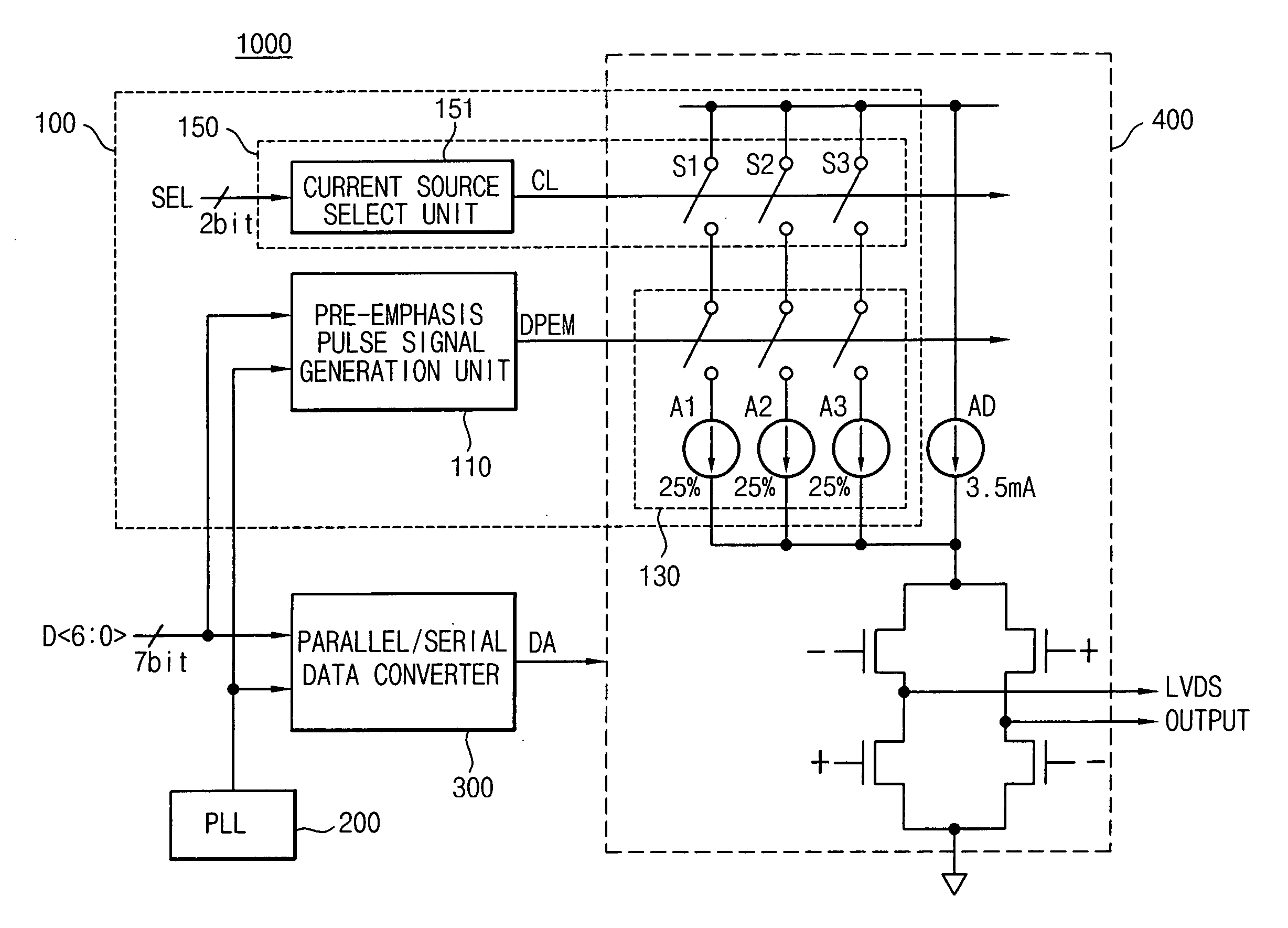
[0032] Example embodiments of the present invention provide a pre-emphasis apparatus of a LVDS transmitter that can improve reliability by generating a pre-emphasis pulse signal using parallel input data received from an external source and a phase clock signal that is used to perform a sampling of the parallel data.
[0034] Example embodiments of the present invention also provide a pre-emphasis method of a LVDS transmitter that can improve the reliability by generating a pre-emphasis signal that determines an amplitude reinforcement location using parallel data received from an external source and a phase clock signal that is used to perform a sampling of the parallel data.

Problems solved by technology

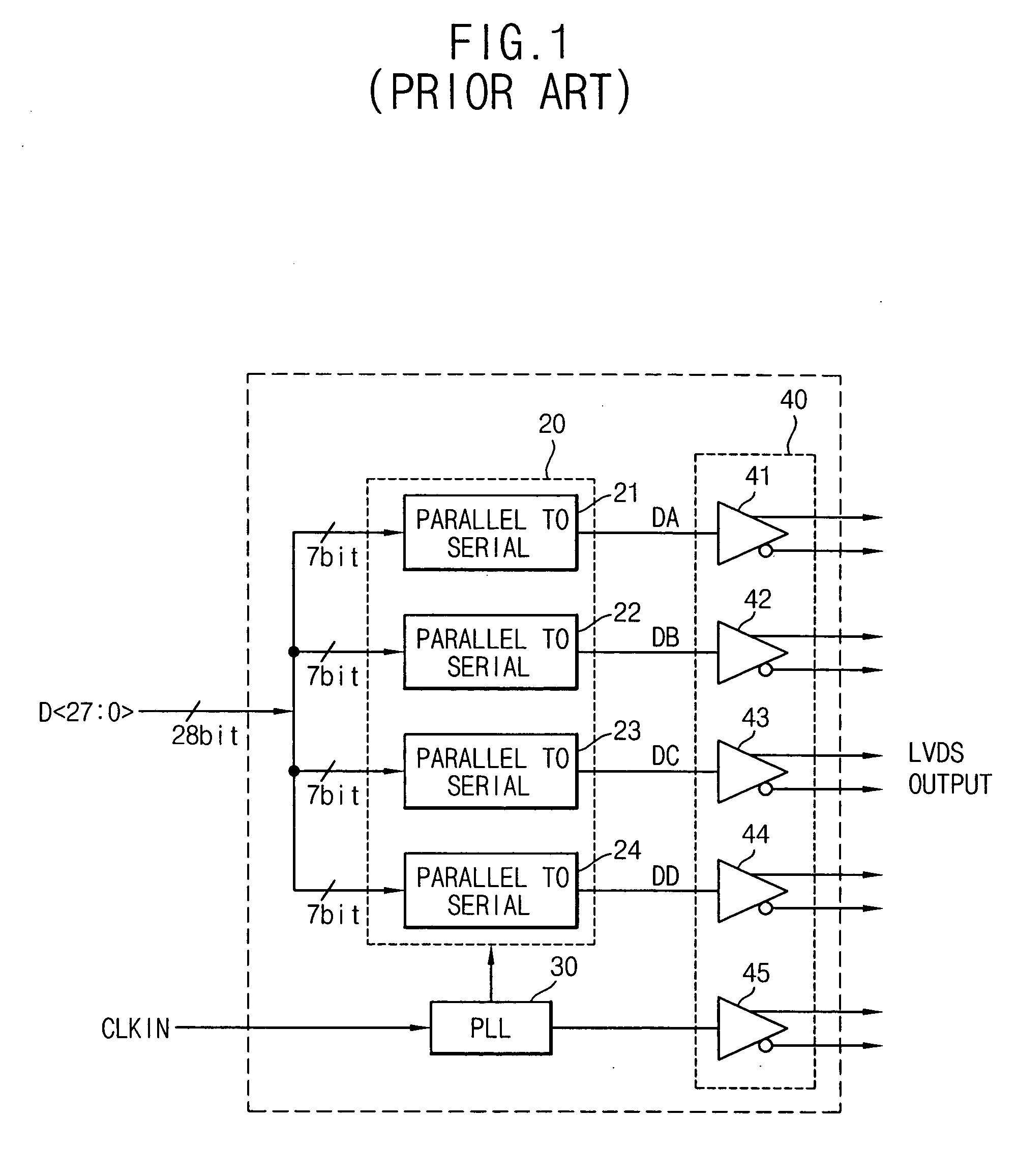
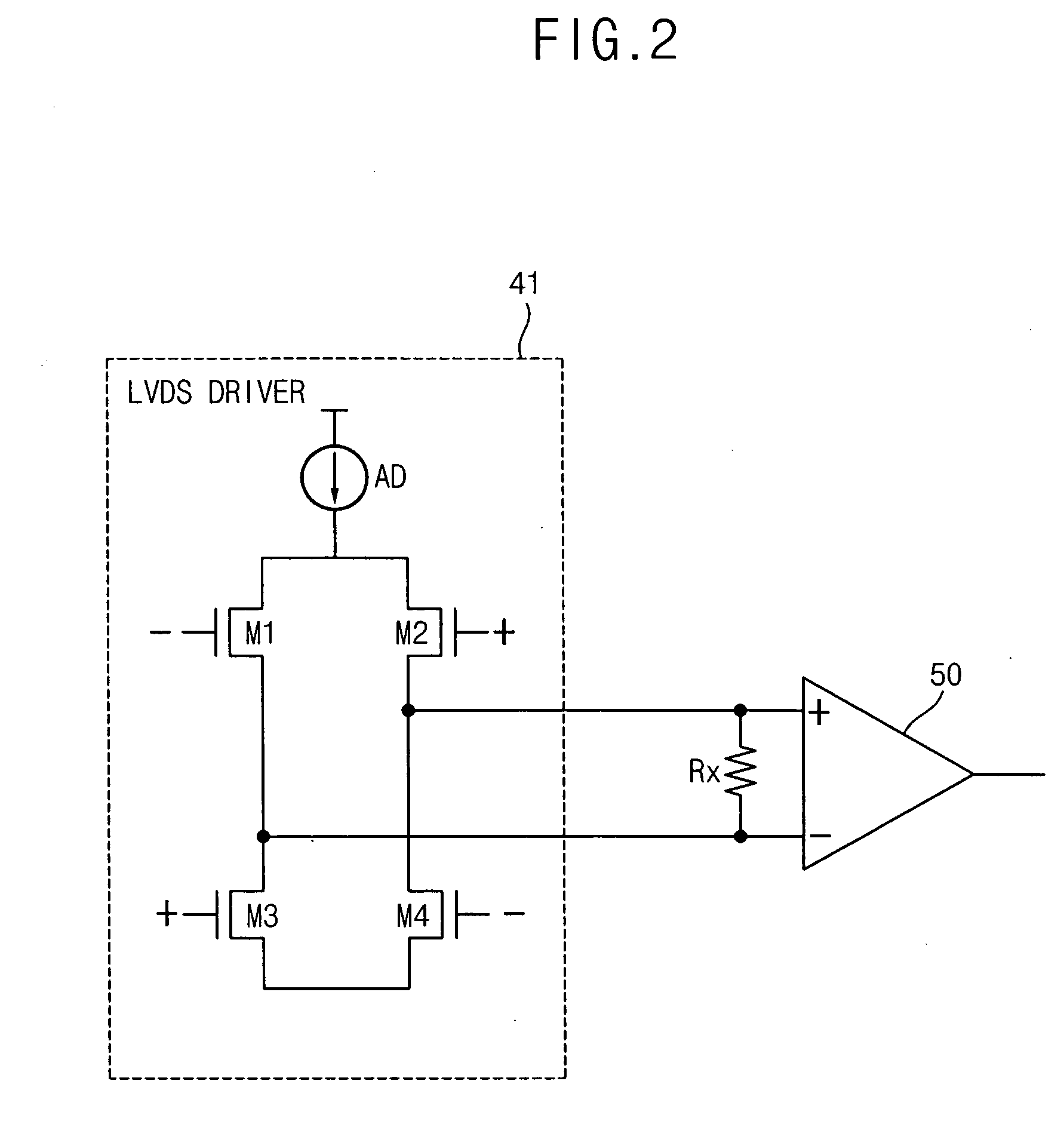
However, such delay time is very sensitive to environmental factors such as process, voltage and temperature (PVT) (i.e., a process change), an operating power voltage change and an operating temperature change.
Accordingly, since the pre-emphasis pulse signal generated by the conventional pre-emphasis pulse signal generation circuit is readily varied by environmental factors and is not regularly maintained due to the characteristics of the delay circuit, it is difficult to perform accurate pre-emphasis, in particular with increasing data transmission rates.

Method used


Image

  • Pre-emphasis apparatus, low voltage differential signaling transmitter including the same and pre-emphasis method
  • Pre-emphasis apparatus, low voltage differential signaling transmitter including the same and pre-emphasis method
  • Pre-emphasis apparatus, low voltage differential signaling transmitter including the same and pre-emphasis method

Examples


Embodiment Construction

[0057] Example embodiments of the present invention are disclosed herein. However, specific structural and functional details disclosed herein are merely representative for purposes of describing example embodiments of the present invention. Example embodiments of the present invention may be embodied in many alternate forms and should not be construed as limited to example embodiments of the present invention set forth herein.

[0058] Accordingly, while the invention is susceptible to various modifications and alternative forms, specific embodiments thereof are shown by way of example in the drawings and will herein be described in detail. It should be understood, however, that there is no intent to limit the invention to the particular forms disclosed, but on the contrary, the invention is to cover all modifications, equivalents, and alternatives falling within the spirit and scope of the invention. Like numbers refer to like elements throughout the description of the figures.

[005...


PUM


Abstract

A pre-emphasis apparatus of a LVDS transmitter includes a pre-emphasis signaling generation unit and a pre-emphasis current output unit. The pre-emphasis signal generation unit generates a pre-emphasis pulse signal based on N parallel data signals received from an external source and N-phase clock signals received from a phase locked loop, where N is an integer greater than 1. The pre-emphasis current output unit provides an additional current for a pre-emphasis operation to a current source of a LVDS driver in response to the pre-emphasis pulse signal generated by the pre-emphasis pulse signal generation unit. The pulse signal for pre-emphasis is generated based on the parallel data signals received from the external source and the multi-phase clock signals, which are output from the phase locked loop for performing a sampling of the parallel data signals.

Description

CROSS-REFERENCE TO RELATED APPLICATIONS [0001] This application claims priority under 35 U.S.C. § 119 to Korean Patent Application No. 2005-74025 filed on Aug. 12, 2005, the contents of which are herein incorporated by reference in their entirety. BACKGROUND OF THE INVENTION [0002] 1. Field of the Invention [0003] The present invention relates to a pre-emphasis apparatus and a pre-emphasis method of a low voltage differential signaling (LVDS) transmitter, and more particularly to a pre-emphasis apparatus and a pre-emphasis method of a LVDS transmitter that can perform pre-emphasis using a parallel data signal and a multi-phase clock signal received from an external source. [0004] 2. Description of the Related Art [0005] A low voltage differential signaling (LVDS) interface system is a circuit having the characteristics of high-speed operation, low current consumption and low electromagnetic interference (EMI), and generally used in various applications such as a semiconductor device...

Claims


Application Information

Patent Timeline
Patent Type & Authority Applications(United States)
IPC IPC(8): H03K19/094
CPCH04L25/0272H03K19/0185H04L25/02
Inventor KIM, JU-HYUNG
Owner SAMSUNG ELECTRONICS CO LTD
Learn More