Apparatus and method for testing visual acuity and fixation control

Inactive Publication Date: 2007-03-22
MARINO JOSEPH A +1
View PDF14 Cites 5 Cited by
  • Summary
  • Abstract
  • Description
  • Claims
  • Application Information

AI Technical Summary

Benefits of technology

[0013] In a preferred embodiment, a VAT apparatus according to the present invention includes a CPU with an associated display device. The VAT apparatus further includes a handheld keypad controller that is operatively associated with the CPU, the keypad controller having a liquid crystal display. Furthermore, the visual acuity testing apparatus according to the present invention includes a foot pedal controller that is operatively associated with the CPU. It is understood that other input devices can be uti

Problems solved by technology

A loss of visual acuity or sharpness is commonly referred to as blurred vision, and results in unclear visual details.
Vision loss is the inability to perceive visual stimuli, which is a significant threat to the quality of life.
The health care professional covers one eye of the patient while the patient attempts to read the VAT chart, and the patient continues to read down the chart to smaller and smaller letters until the patient is no longer able to read the letters because the letters appear too blurry.
This makes this particular system difficult to learn and cumbersome to operate.
In addition to the difficulties of learning and operating this system, physicians utilizing these hand-held controllers have reported considerable unit failures within five years.
Also, they have an inability to accurately use this system for visual acuity tests in small exam rooms (less than ten feet).
In addition to the complexities of numerous keystrokes to initiate testing and the large number of acuity tests, as well as the small exam room miscalibration, another problem exists with this technology.
In addition, since this system does not include an LCD display, the health care professional does not know what test is coming up until it appears on the monitor.
This has been found to be inconvenient, more prone to error and more t

Method used


Image

  • Apparatus and method for testing visual acuity and fixation control
  • Apparatus and method for testing visual acuity and fixation control
  • Apparatus and method for testing visual acuity and fixation control

Examples


Embodiment Construction

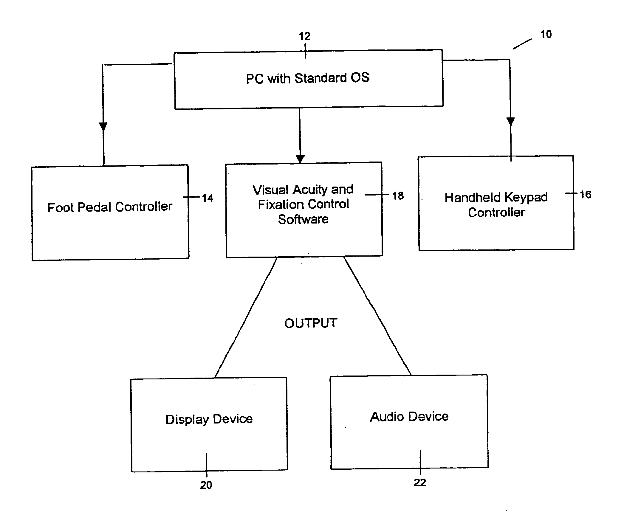
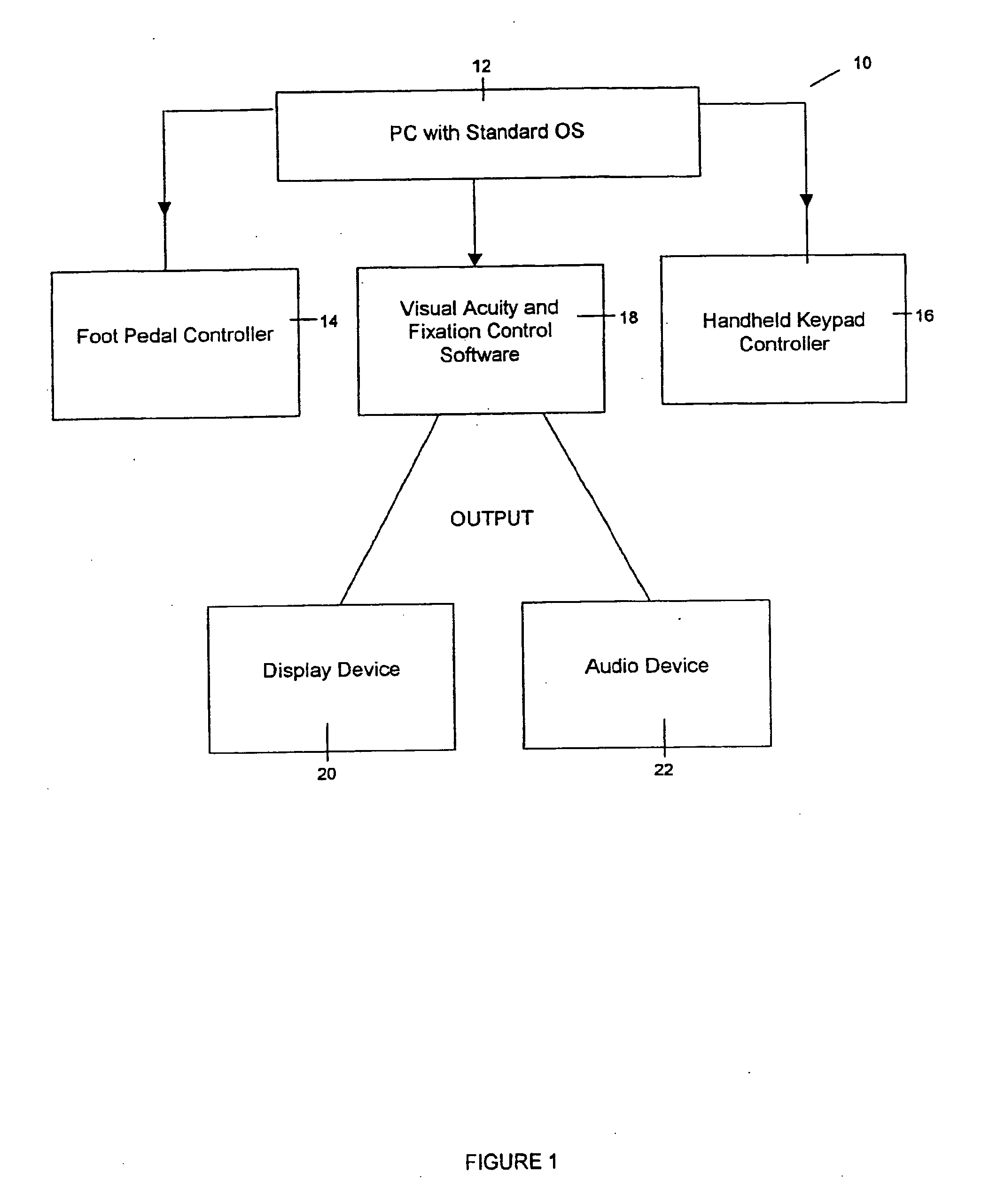
[0032] In accordance with one aspect of the present invention, an apparatus and method for conducting a visual acuity test (VAT) is provided. FIG. 1 schematically illustrates a computer-based system in accordance with a preferred embodiment of the present invention. The system includes a conventional computer 12 or central processing unit (CPU) with an operating system, such as Windows®. It is contemplated, however, that the present invention can be designed to be compatible with other computer operating systems, such as Apple®, Linux®, UNIX and so forth. The apparatus comprises a display device 20 and audio device 22 used in conjunction with a computer 12, a first controller or foot pedal controller 14, a second controller or handheld keypad controller 16 used in conjunction with control software 18 to provide video and audio output to a display device 20 and audio device 22, respectively. The method according to the present invention includes the use of a particular arrangement of...


PUM


Abstract

A method and apparatus for conducting a visual acuity test are provided. The method includes displaying a visual acuity test on a display device (20) that is initiated by a controller (16) such as a handheld keypad controller (16), which is operatively associated with the computer-processing unit (12). The patient's eye is fixated using an eye fixation assessment on a display device during portions of the visual acuity test and is initiated by a controller such as a foot pedal controller (14), which is operatively associated with the CPU. Contrast sensitivity can also be evaluated on the display device by selectively altering the contrast of an image and background on the display device (20).

Description

CLAIM OF PRIORITY [0001] This application claims priority from U.S. Provisional Application Ser. No. 60 / 277,691, filed on Mar. 21, 2001.FIELD OF THE INVENTION [0002] The present invention relates to assessing visual acuity. It finds particular application in conjunction with testing a patient in an ophthalmology examination to determine certain astigmatisms, eye diseases and disorders. However, it is to be appreciated that the present invention is also amenable to other like applications. BACKGROUND OF THE INVENTION[0003] In an ophthalmology examination, a health care professional must complete a broad range of tests in order to assess visual acuity, including the presence of astigmatisms, eye diseases and disorders. A loss of visual acuity or sharpness is commonly referred to as blurred vision, and results in unclear visual details. Vision loss is the inability to perceive visual stimuli, which is a significant threat to the quality of life. Therefore, a visual acuity test is very ...

Claims


Application Information

Patent Timeline
IPC IPC(8): A61B3/04A61B3/028A61B3/032A61B3/06
CPCA61B3/0033A61B3/022A61B3/063A61B3/032A61B3/028
Inventor MARINO, JOSEPH A.NORDSTROM, STEVEN B.
Owner MARINO JOSEPH A
Why Eureka
Try Eureka