Led illumination device

a technology of led illumination and led light, which is applied in the direction of lighting support devices, coupling device connections, lighting and heating apparatus, etc., can solve the problems of increasing the cost of metal molds, increasing the total cost, and short life of the lamp, so as to prevent the reliably removed cover, the design flexibility is increased, and the effect of easy extension

Inactive Publication Date: 2007-03-22
YAZAKI CORP
View PDF8 Cites 61 Cited by
  • Summary
  • Abstract
  • Description
  • Claims
  • Application Information

AI Technical Summary

Benefits of technology

[0041] In view of above described problems, an object of this invention is to provide an LED illumination device, which can be easily exten

Problems solved by technology

However, these first to third embodiments have problems below.
Further, if the illuminating lamp 56 is an incandescent lamp, there is another problem that such a lump has a short life because of its high power consumption and high heating value.
However, there is a problem that said illumination device 60 cannot flexibly adapt to an increase or a decrease in the number of the LED chips 64, so that the lamp body 61, the substrate 63, and the lens 65 should be reformed and a total cost, including a cost for metal molds, increases.
Further, since the illumination device 70 is connected to the wire harness 75 through the joint connector 71, the branch line 72, and the module connector 73, there is a problem that the number of the parts is large and a total cost increases.
Further, it is troublesome and time-consuming to install an additional illumination device 70.
However, there is a problem that, for arran

Method used


Image

  • Led illumination device
  • Led illumination device
  • Led illumination device

Examples


Embodiment Construction

[0124] In the following, the present invention will be explained with reference to the attached drawings.

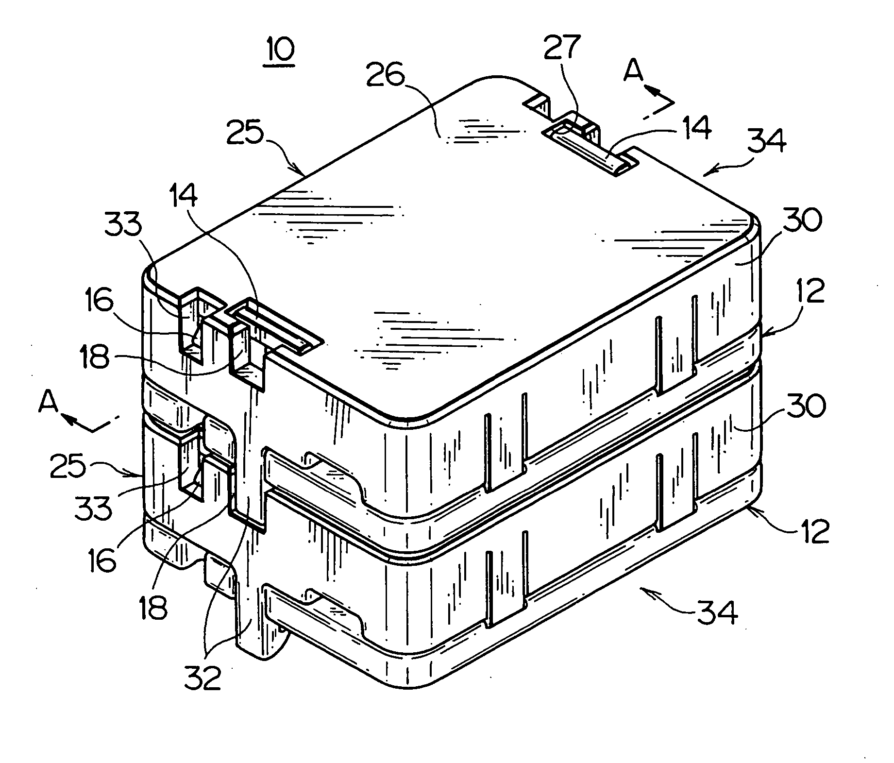
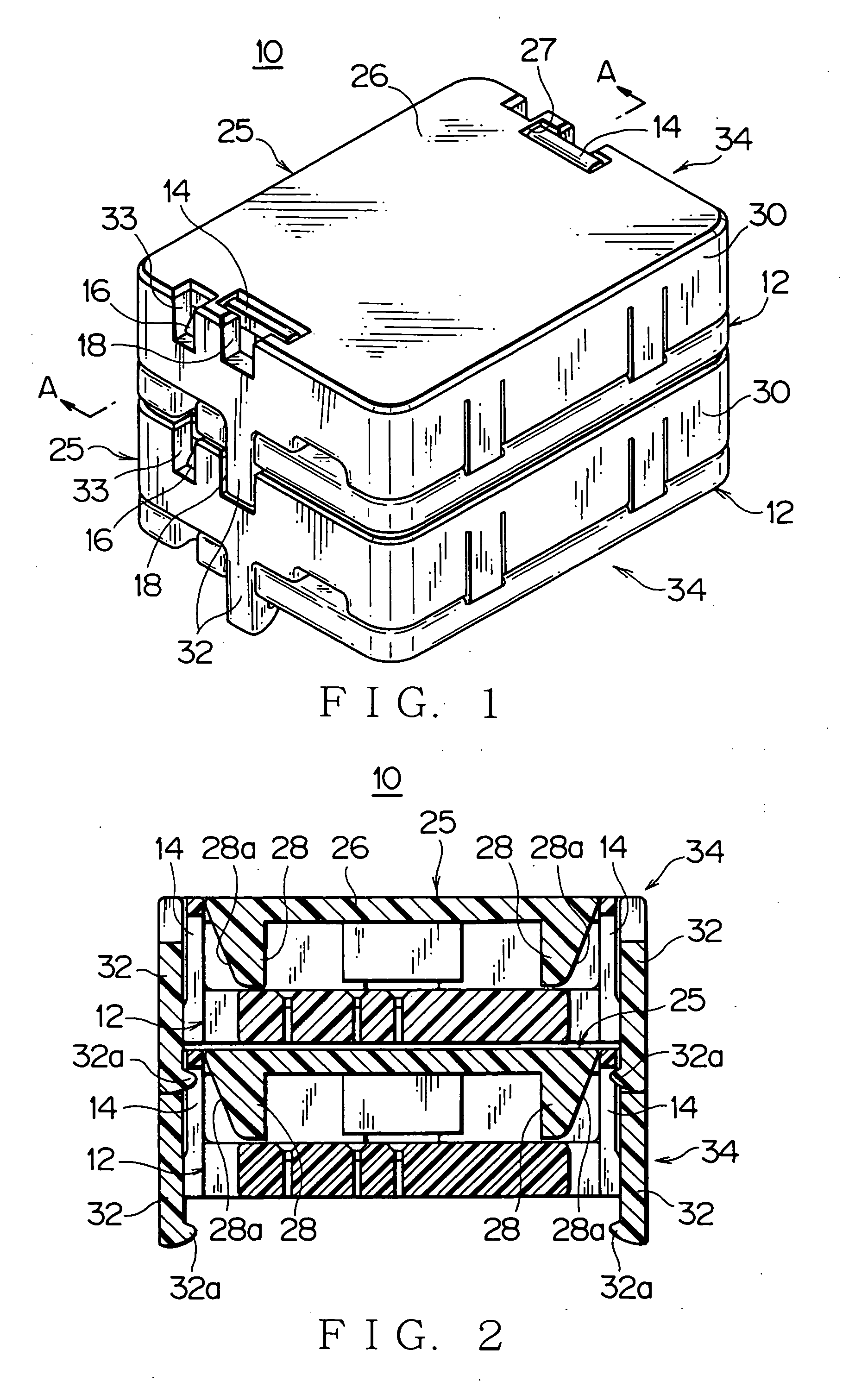
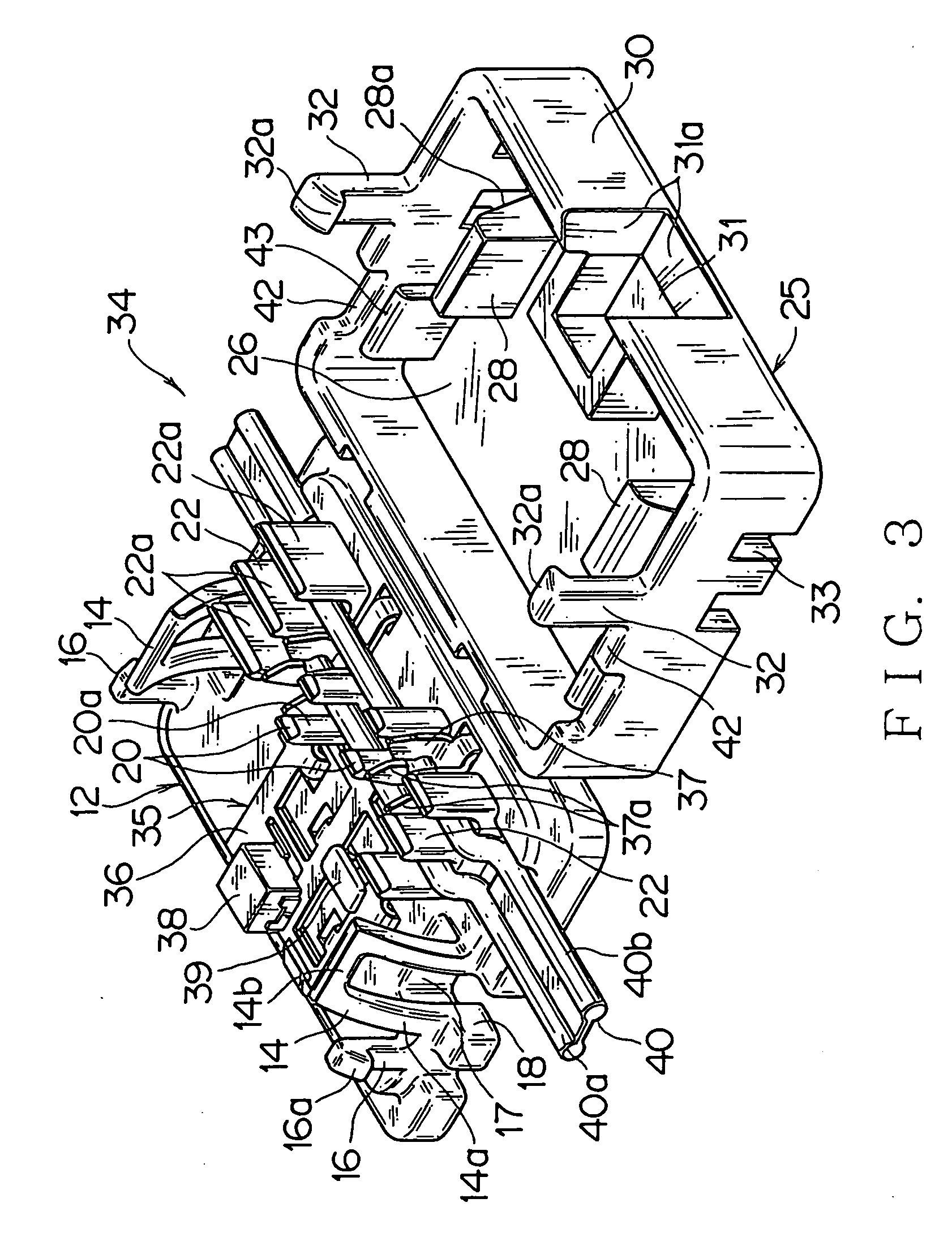
[0125] FIGS. 1 to 6 show one embodiment of an LED illumination device according to this invention.

[0126] The LED illumination device 10 is formed by lower and upper LED lamp modules 34 coupling together, used for an interior roof lamp, a map lamp and the like in a vehicle for purposes of illuminating an interior of the vehicle, illuminating interior of small containers, such as a console box, a glove box, a handy pocket or an ash tray, or illuminating a cup holder, or a floor of the vehicle.

[0127] The LED illumination device 10 can be easily extended more, miniaturized, standardized, and prevent reliably a cover 25 from uncovering a base 12.

[0128] The LED illumination device 10 is firstly characterized by the followings. The LED illumination device 10 is formed by coupling LED lamp modules 34 in a vertical direction. Said LED lamp module 34 comprises the base 12, a bus bar ci...


PUM


Abstract

An LED illumination device includes LED lamp modules 34 coupled in a vertical direction. Each of said LED lamp modules 34 includes a base 12, a bus bar circuit 35 formed on the base 12, and a cover 25 connected to the base 12 to cover the bus bar circuit 35. A locking frame 14 (coupling portion) to be coupled with the upper LED lamp module 34 is formed on said base 12. A locking arm 32 (mating coupling portion) to be coupled with said locking frame 14 on the base 12 of the lower LED lamp module 34 is formed on said cover 25. Further, a guiding groove 18, into which said locking arm 34 is inserted, is formed on said base 12 near the locking frame 14, and a guiding hole 27, into which said locking frame 14 is inserted, is formed on the cover 25 near the locking arm 32.

Description

TECHNICAL FIELD [0001] This invention relates to a compact LED illuminating device being used for an interior roof lamp, a map lamp and the like in a vehicle for purposes of illuminating an interior of the vehicle, illuminating interior of small containers, such as a console box, a glove box, a handy pocket or an ash tray, or illuminating a cup holder, or a floor of the vehicle. [0002] Further, this invention also relates to an LED lamp module with the use of LED, and a lamp module assembly having more than one LED lamp module connected to electric wires. BACKGROUND ART [0003]FIG. 7 shows one embodiment of a conventional illuminating device. (Patent Document 1) [0004] This illuminating device 50 continually illuminates interiors of an ash tray 51 and a console box 53, characterized in that an illuminating lamp 56 is arranged at a position where the ash tray 51 being pulled out is prevented from blocking light path from the illuminating lamp 56. [0005] The ash tray 51 is arranged ove...

Claims


Application Information

Patent Timeline
IPC IPC(8): H01R33/00B60Q1/26B60Q3/02F21S2/00F21V17/16F21V21/002F21V27/00
CPCB60Q1/2696B60Q3/0203B60Q3/0289F21S2/005F21Y2101/02F21V21/002F21V27/00F21W2101/08F21V17/164B60Q3/51B60Q3/78F21Y2115/10F21W2106/00Y10S362/80
Inventor CHIBA, SHINGOMATSUSHITA, HARUYUKIOKABE, TOSHIAKI
Owner YAZAKI CORP
Why Eureka
Try Eureka