Fire protection coating for FRP-reinforced structure

a technology of reinforced structure and fire protection coating, which is applied in the direction of fireproofing, weaving, layered products, etc., can solve the problems of affecting the safety of the structure, delay the ignition of the structural member, etc., and achieve the effect of reducing the thickness, reducing the cost, and slowing the heating of the underlying structural member

Inactive Publication Date: 2007-03-22
FYFE EDWARD R
View PDF1 Cites 14 Cited by
  • Summary
  • Abstract
  • Description
  • Claims
  • Application Information

AI Technical Summary

Benefits of technology

[0017] In the event of a fire, the insulation layer slows the heating of the underlying structural member. Residual moisture within the insulation layer traps heat and further delays ignition of the structural member.
[0018] Using this method and combination of materials, a fire rating of 4 hours (ASTM E119—Concrete Under Load) can be achieved with a coating thickness of only 1 inch of SFRM and 0.01 inch of diffusion barrier. This is a substantial decrease in thickness compared to conventional fire protection coatings, making it lower cost and especially valuable for use on existing structures that have been reinforced with retrofitted fiber / resin composite materials.

Problems solved by technology

Residual moisture within the insulation layer traps heat and further delays ignition of the structural member.

Method used


Image

  • Fire protection coating for FRP-reinforced structure
  • Fire protection coating for FRP-reinforced structure
  • Fire protection coating for FRP-reinforced structure

Examples


Embodiment Construction

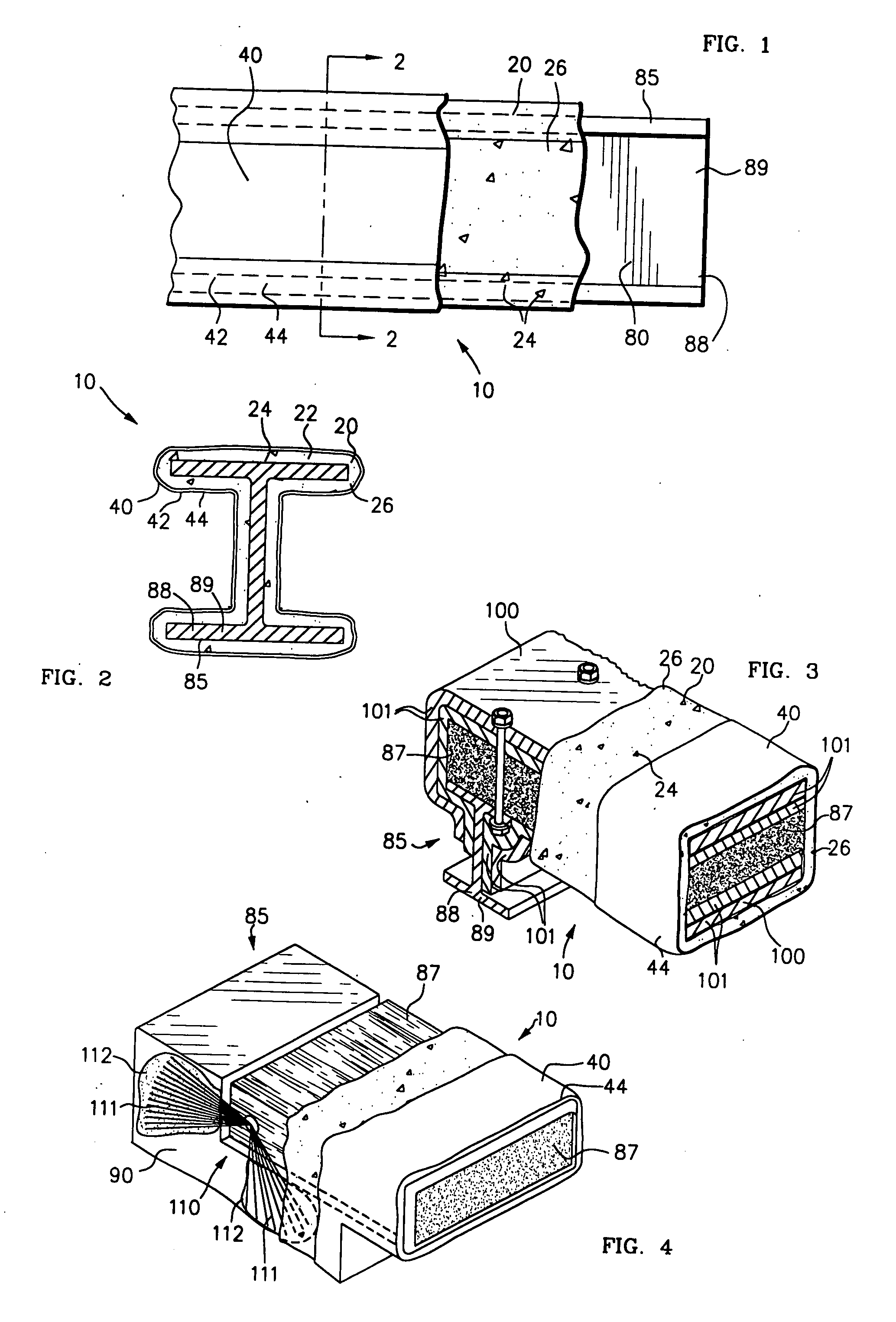
[0028]FIG. 1 is a side elevation view, partly cut away, of a steel girder 88, such as I-beam 89, with fire protection coating 10 applied according to the method of the present invention. FIG. 2 is a sectional view, taken on line 2-2 of FIG. 1. Fire protection coating 10 includes an insulation layer 20 and a diffusion barrier layer 40.

[0029]FIG. 3 is a perspective view, partly cut away, of fire protection coating 10 over a structural member 85 that includes an 1-beam 89, a beam 87, and reinforcement 100. Reinforcement 100 consists of a plurality of fiber / resin composite panels or wraps 101 wrapped upon and attached to I-beam 89 and beam 87. Panels 101 have been added to existing structural member 85 to provide additional resistance to lateral forces, such as from earthquakes, high winds, or explosions. Reinforcement 100 is typical of retrofitted fiber / resin composite seismic reinforcement to an existing structure. Composite panels 101 are typically of epoxy-impregnated fiberglass.

[...


PUM

PropertyMeasurementUnit
thickaaaaaaaaaa
thickaaaaaaaaaa
thickaaaaaaaaaa

Abstract

A fire protection coating 10 includes insulation layer 20 including at least 20% free moisture. Insulation layer 20, preferably a vermiculite/gypsum mixture 26, is applied such as by spraying a water slurry of the mineral particles to structural member 85. Before the free moisture can evaporate, diffusion barrier 40, such as artificial stone formulation 44, is applied over the moist vermiculite/gypsum mixture 26. Moisture is retained within vermiculite/gypsum mixture 26 indefinitely and is released in the event of a fire to help cool and prolong the efficacy of fire protection coating 10.

Description

CROSS REFERENCE TO RELATED APPLICATIONS [0001] This application is a Continuation-in-Part of application Ser. No. 10 / 383,265, filed Mar. 5, 2003. FIELD OF THE INVENTION [0002] This invention relates to fire protection of structures, and more specifically to fire protection coating applied to structural members of a finished building reinforced with fiber / resin composite materials. BACKGROUND OF THE INVENTION [0003] In large structures, including bridges, tunnels, and buildings, the load-bearing structural members are generally of concrete or steel. Concrete is usually considered inherently fire-resistant because it is non-combustible. Steel is also non-combustible, but high temperature from a fire weakens steel greatly and can cause it to fail. For this reason, steel is required to be “fire-proofed” when used in a large structure. Some concrete structures, such as tunnels, also require fire-proofing. [0004] Many concrete structures have had reinforcement layers added to them to impr...

Claims


Application Information

Patent Timeline
Patent Type & Authority Applications(United States)
IPC IPC(8): B32B5/02C09D5/18E04B1/94
CPCC09D5/18E04B1/944E04B1/94Y10T442/20
Inventor FYFE, EDWARD R.
Owner FYFE EDWARD R
Why Eureka
Try Eureka