Fused silica glass and method for making the same

Active Publication Date: 2007-03-22
CORNING INC
View PDF9 Cites 10 Cited by
  • Summary
  • Abstract
  • Description
  • Claims
  • Application Information

AI Technical Summary

Benefits of technology

[0064] The present invention has the advantages of being capable of producing H2-loaded silica glass material suitable for use as refractive elements of lithographic applications operating at below about 300 nm, such as at about 248 nm and 193 nm,

Problems solved by technology

They mostly teach hydrogen loading at high pressure, and sometimes at high temperature, which are undesirable.
Moreover, they invariable require long hydrogen loading time to achieve the stated hydrogen concentra

Method used


Image

  • Fused silica glass and method for making the same
  • Fused silica glass and method for making the same
  • Fused silica glass and method for making the same

Examples


Example

Example 1

[0144] Comparisons are made here between the first method of the present invention which utilizes a uniform partial pressure of hydrogen and the second method of the present invention which utilizes variable partial pressures of hydrogen. Hydrogen loading using the first method, as was discussed in section A above, results in a single minimum at the center of the lens blank. Other examples of calculated hydrogen gradients are presented in TABLE III below with one example of a hydrogen gradient shown in FIG. 8 for specific cylindrical glass geometry of 270 mm diameter×60 mm thick disc hydrogen loaded at 600° C. TABLE IIILoading time at full[H2][H2]Max ExternalMaxtemperatureEdgeCenter[H2]Gradient(Minutes)(Days)(×1017 molecules / cm3)100,000691.00.8310.08150,0001031.00.9310.03200,0001381.00.9810.01

Example

Example 2

[0145] This example uses the second method of the present invention (variable H2 partial pressure). Likewise, it assumes loading a 270 mm×60 mm silica disk at 600° C. The parameters and results are shown in TABLE IV. TABLE IV shows that the second method of the present invention can achieve the same Δ[H2] of ˜0.15×10¹⁷ molecules / cm3 in around half the time needed for the first method in this particular example. TABLE IVLoading time at full[H2][H2]Max ExternalMax [H2]temperatureMaxMinΔ[H2]ConcentrationGradient(Minutes)(Days)(×1017 molecules / cm3)50,000351.250.960.2950.1550,000351.040.890.1580.07

[0146]FIG. 9 shows an example of a distribution achieved by the second method of the present invention which utilizes a single crossover pressure variation. The pressure profile of the single crossover pressure variation used is illustrated in FIG. 10. FIG. 11 shows an example of final H2 concentration distribution by the second method of the present invention which utilizes a double...

Example

Example 3

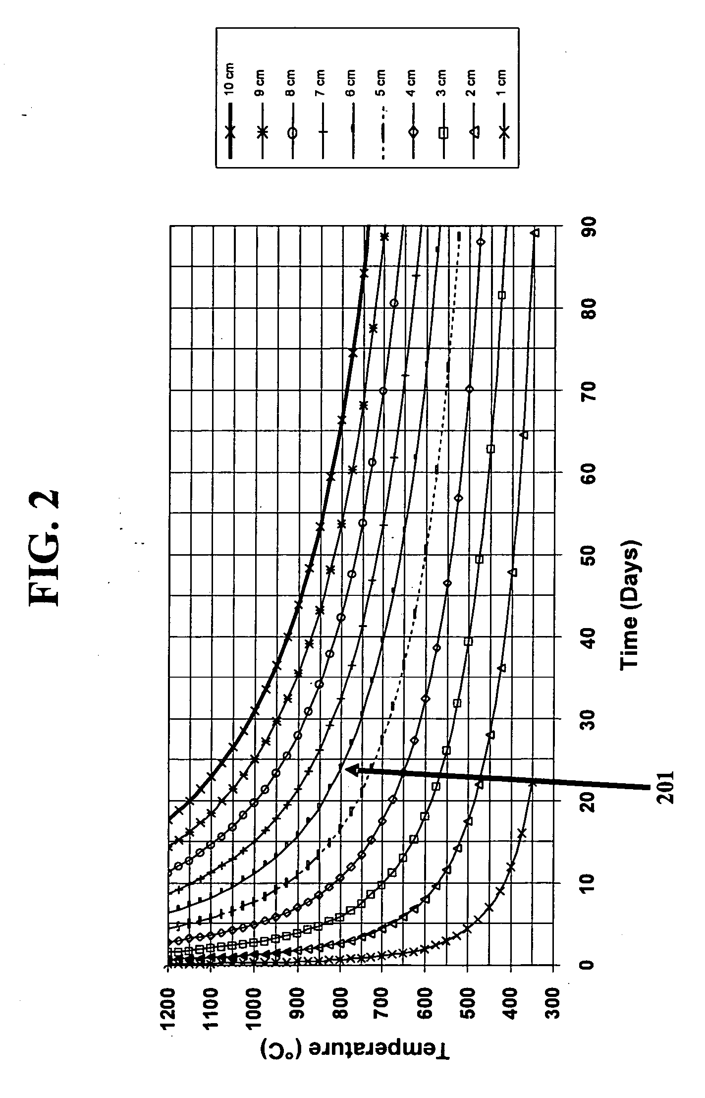
[0148] The experiment in this example was performed to validate the concept that varying the surface concentration of hydrogen during loading could significantly reduce loading time. Two cases were examined. Case I refers to glass that is loaded by “conventional loading”. Here, conventional loading is defined as a constant surface concentration of H2 during loading. FIG. 13 shows model predictions for loading a 20×25×100 mm3 bar at 350° C. for 89.2 days at constant loading partial pressure of H2. The results show that after the 89.2 days, a surface concentration of 0.7×10¹⁷ molecules / cm3 H2 would be expected on the surface of the glass while 0.59×10¹⁷ molecules / cm3 H2 would be expected in the sample center. The model prediction is based on the following equation:

DH2=(5.65×10⁻⁴)·exp(−5220 / T)(cm2 / sec)

where DH2 is the diffusivity of H2 at temperature T (in Kelvin).

[0149] Case II refers to an example of accelerated loading procedures which vary the surface concentration of H...


PUM

PropertyMeasurementUnit
Temperatureaaaaaaaaaa
Fractionaaaaaaaaaa
Partial pressureaaaaaaaaaa

Abstract

Disclosed are methods for hydrogen loading silica glass and silica glass comprising loaded H2. The methods can lead to H2 gradient in the glass material. Alternatively, the method may involve the use of varying H2 partial pressure of H2 in the atmosphere. Both can result in expedited hydrogen loading process.

Description

CROSS-REFERENCE TO RELATED APPLICATIONS [0001] The present invention claims priority to U.S. Provisional Patent Application Nos. 60 / 718,009, filed Sep. 16, 2005 and entitled “Low Distortion Silica Glass for the DUV,” and 60 / 755,807, filed Dec. 30, 2005 and entitled “Fused Silica Glass and Method for Making the Same,” the contents of both of which are relied upon and incorporated herein by reference in their entirety.FIELD OF THE INVENTION [0002] The present invention relates to fused silica glass and method of making the same. In particular, the present invention relates to fused silica glass with low LIWFD, low induced absorption, and low refractive index variation, and method of hydrogen-loading the precursor glass for making the desired fused silica glass. The present invention is useful, for example, in making high purity fused silica glass for use in lithography devices operating in deep UV and vacuum UV wavelength regions. BACKGROUND OF THE INVENTION [0003] High purity silica ...

Claims


Application Information

Patent Timeline
IPC IPC(8): C03B19/06C03C3/06C03B32/00
CPCC03B19/1453C03B32/00C03B2201/07C03B2201/075C03B2201/21G03F7/708C03C3/06C03C2201/21C03C2201/23C03C2203/54C03B2201/23Y10S501/905
Inventor HARPER, BRIAN LEEHRDINA, KENNETH EDWARDLASALA, JOHN EDWARD
Owner CORNING INC
Why Eureka
Try Eureka