
Fordable modular light array

Inactive Publication Date: 2007-03-29
SEGAN
View PDF6 Cites 57 Cited by
  • Summary
  • Abstract
  • Description
  • Claims
  • Application Information

AI Technical Summary

Benefits of technology

[0010] The display system according to the invention offers the advantage of being light weight and easy to handle and store, while still being of substantial size when opened so that the panels are coplanar.
[0011] The elimination of PCB's makes the system more flexible and less prone to damage when flexed. The use of translucent caps over the LED's simulates a larger bulb which improves the aesthetics when viewed at a distance.
[0012] The openings in the panel not only reduce weight but make it pervious to the wind, so that heavy duty mounting hardware is not required. The openings also facilitate mounting by making the sign easy to affix string or wire virtually anywhere on the sign.
[0013] Weight is further reduced by removing the transformer and power supply from the sign, preferably locating these components in the supply line between a controller on the first panel and a plug designed for a wall outlet. The transformer reduces the line voltage (e.g. 120 V) to a safe low voltage (e.g. 6 V, 3 A) for the LED's, so that heavy duty insulation of the wires on the support member is not necessary.
[0016] The primary market for the display system according to the invention is expected to be in holiday displays for consumer use. A non-repeating Christmas routine of 10 to 15 minutes can very easily be provided to the display panels with existing chip technology. The controller may be provided with switches to change to a motif for another holiday, such as Halloween.

Problems solved by technology

These signs are typically intended for fixed, relatively permanent installation and may be expensive.
The overall size is limited, because the PCB's are too fragile to be made in large sizes.
Large PCB's are also expensive for consumer applications.
Large display signs are also cumbersome to handle, require significant storage space, and may be heavy.

Method used


Image

  • Fordable modular light array
  • Fordable modular light array
  • Fordable modular light array

Examples


Embodiment Construction

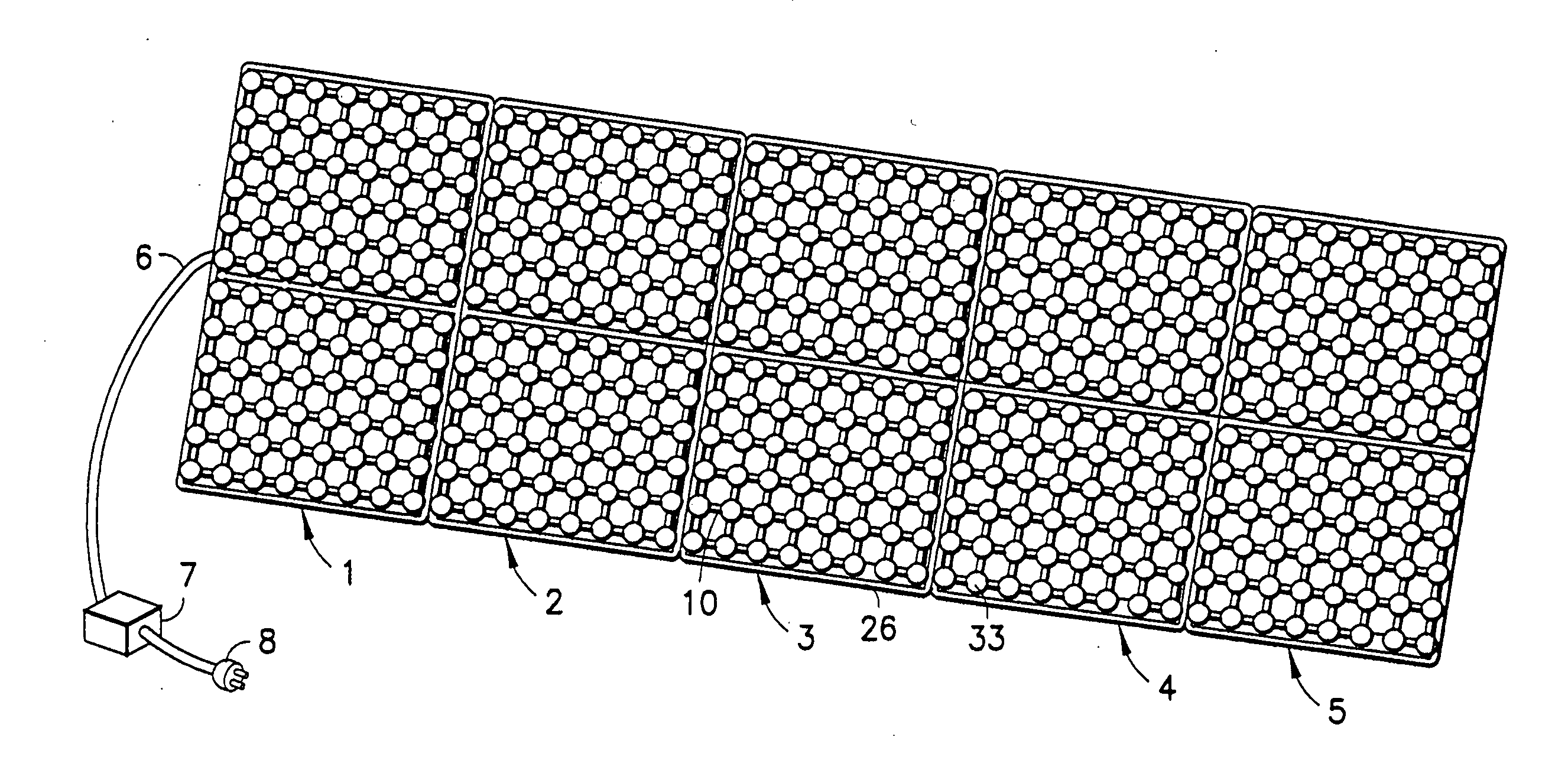
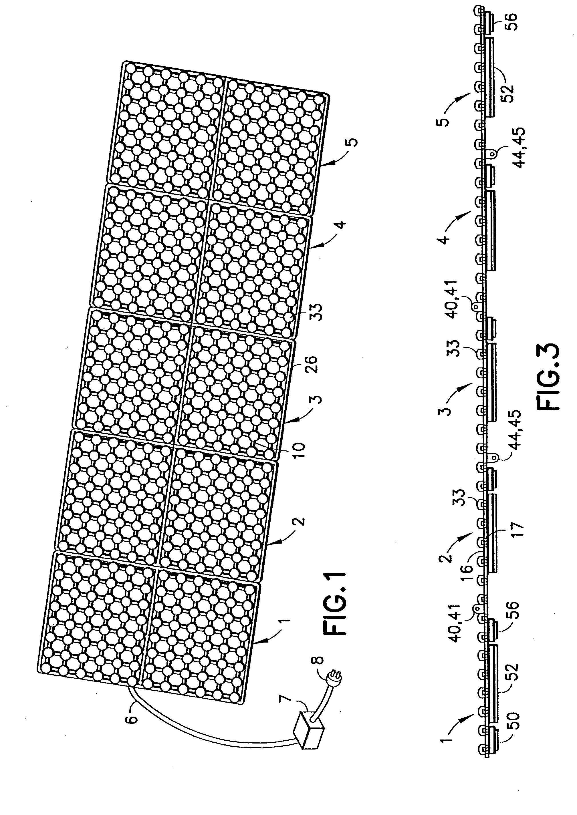
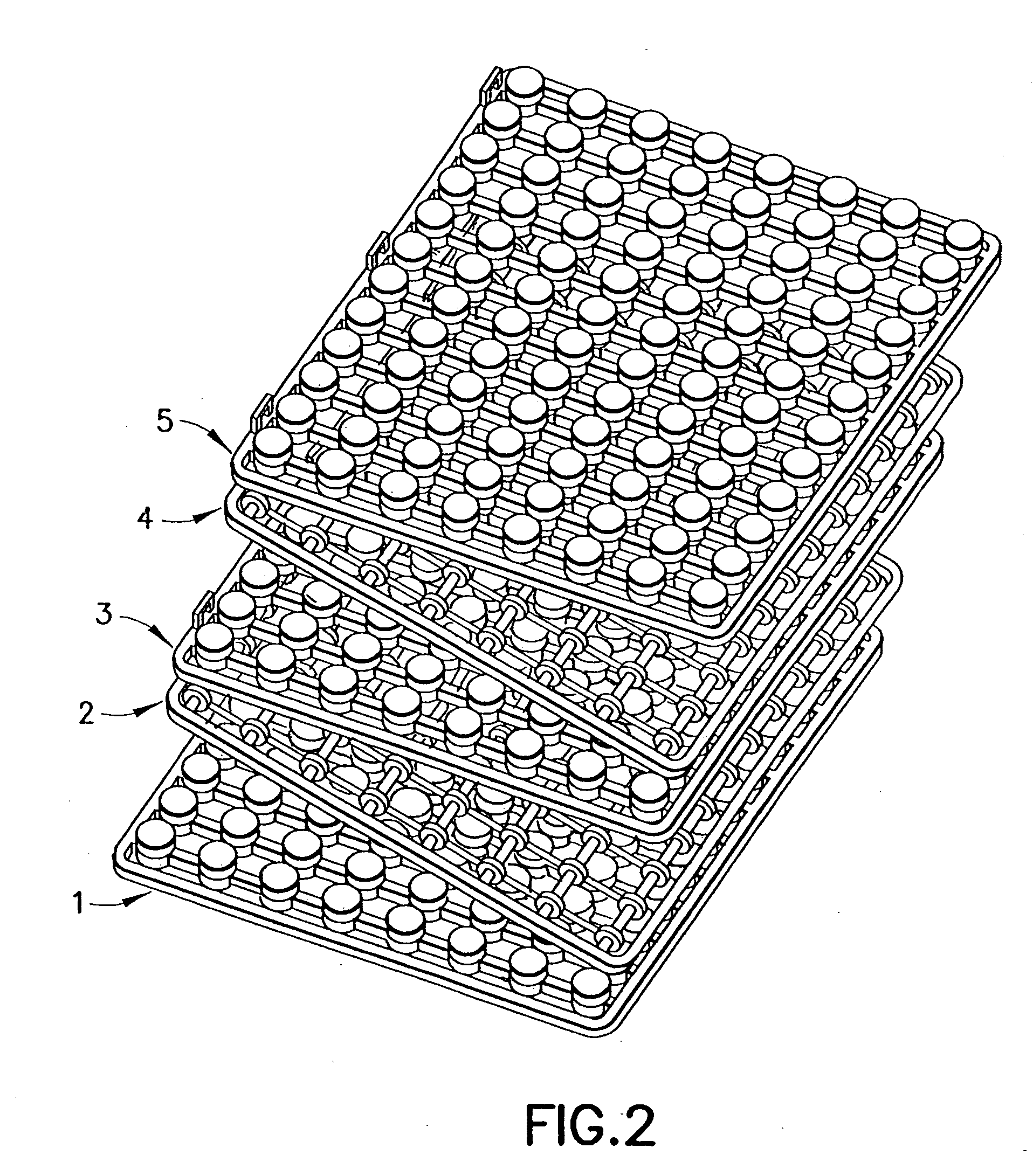
[0033]FIG. 1 shows a plurality of lighting panels 1-5 which are connected together serially to form a display sign having a power cord 6, a transformer 7 in the power cord, and a plug 8. Each panel 1-5 includes an injection molded plastic support member 10 in the form of an open mesh surrounded by a frame 26 and carrying light caps 33 in an array of rows and columns. In the example shown, the light caps 33 on each panel are arranged in a 12×8 array, and cover respective lights mounted in the support member. The frames 26 are connected by hinges and are also provided with latches to lock the panels in a coplanar relationship. In a currently contemplated embodiment, each panel is 12″ wide by 18″ high, so that the display sign is 5′ wide by 18″ high and includes 480 LED's, which are located under the cap members and may be collectively referred to as lights.

[0034] The panels are substantially identical and modular so that any number can be connected together serially to form a display...


PUM


Abstract

A display system comprising a plurality of display panels (1-5) connected together serially, each panel including a planar support member (10) having a plurality of parallel first bars (12) connected to a plurality of parallel second bars (14) at intersections (20) to form an open mesh having a front surface (16), a rear surface (17), and a plurality of openings (18) extending between the surfaces (16, 17). A plurality of LED's (30) are mounted in apertures (21) at respective intersections (20), each LED (30) being covered with a translucent cap (33) on the front surface (16) and having a pair of terminals (32) connected to a grid of mutually isolated wires (54, 58) located in channels (13, 15) in the rear surface (17). The panels (1-5) are connected by hinge members (40, 41, 44, 45) which permit the panels to be folded into a stack.

Description

BACKGROUND OF THE INVENTION [0001] 1. Field of the Invention [0002] The invention relates to a display system of the type having an array of lights in rows and columns which can be selectively powered to display textual messages and graphic images. [0003] 2. Description of the Related Art [0004] Display signs of all sizes are available for commercial purposes. These signs are typically intended for fixed, relatively permanent installation and may be expensive. [0005] As LED technology has progressed and more luminous LED's have become available in a greater variety of colors, LED based display signs have been developed for consumers. These signs typically employ LED's mounted on one or more printed circuit boards (PCB's). The overall size is limited, because the PCB's are too fragile to be made in large sizes. Large PCB's are also expensive for consumer applications. [0006] Large display signs are also cumbersome to handle, require significant storage space, and may be heavy. When m...

Claims


Application Information

Patent Timeline
IPC IPC(8): G09F13/22G09F3/04G09GG09G3/32
CPCG09F9/33G09G2300/026G09G3/32
Inventor SEGAN, MARC H.STRAUSS, GARY
Owner SEGAN
Features
  • Generate Ideas
  • Intellectual Property
  • Life Sciences
  • Materials
  • Tech Scout
  • Unparalleled Data Quality
  • Higher Quality Content
  • 60% Fewer Hallucinations
Learn More