
Brazed joint torque test apparatus and methods

a brazed joint and torque testing technology, applied in the direction of force/torque/work measurement apparatus, manufacturing tools, instruments, etc., can solve the problems of undesirable failure of such a brazed joint and insufficient joint production, and achieve the effect of preventing tool rotation

Inactive Publication Date: 2007-03-29
THE BOEING CO
View PDF8 Cites 12 Cited by
  • Summary
  • Abstract
  • Description
  • Claims
  • Application Information

AI Technical Summary

Benefits of technology

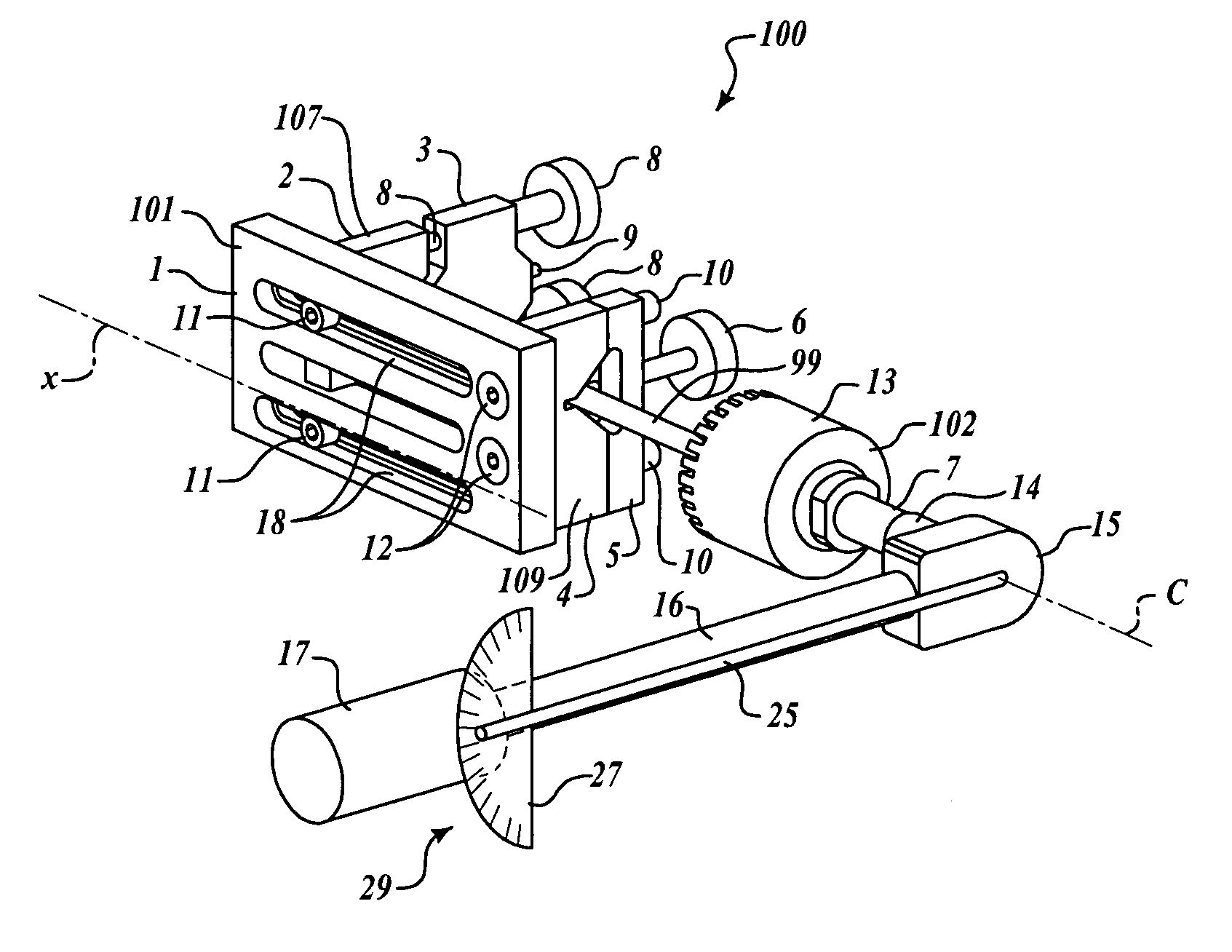
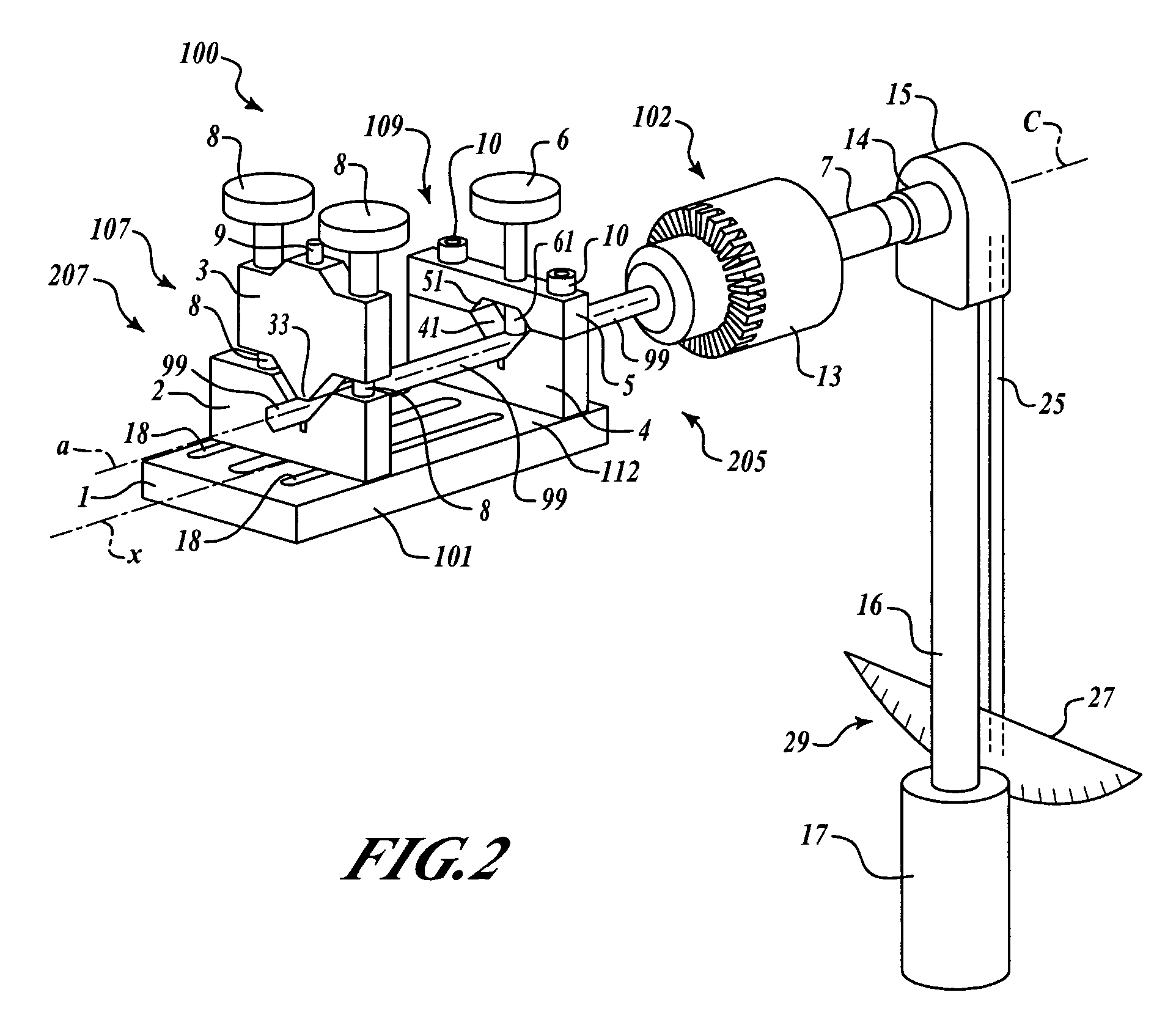
[0009] In another embodiment, a testing torque may be imparted to a cylindrical tool while the tool is clamped in a clamping appliance. The tool has a driven end including a shank and a working end in opposed relation along the axis. The clamping appliance is configured to clamp the tool to prevent rotation of the tool. A shank of the tool is clamped in a chuck. The chuck has a adapter defining a void configured to engagingly receive a socket drive shaft. A torque wrench having a lever arm and a socket driver shaft is engaged by insertion of the socket drive shaft into the void. A torque is imparted to the cylindrical tool about its axis by suitably imparting a force on the lever arm. The quantum of torque imparted is measured based upon operation of the torque wrench.

Problems solved by technology

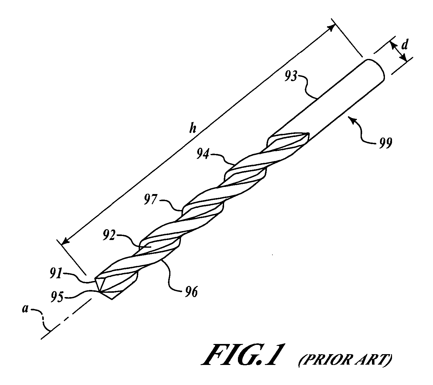
In some instances, however, brazing a joint between the extending shaft (not shown) and the drill shank 93 may not produce a joint adequate to withstand the torque necessary to rotate the cutting edges 91 against the material.
Failure of such a brazed joint is undesirable for a number of reasons.

Method used


Image

  • Brazed joint torque test apparatus and methods
  • Brazed joint torque test apparatus and methods
  • Brazed joint torque test apparatus and methods

Examples


Embodiment Construction

[0015] The present invention relates to methods and apparatus for torque-testing of brazed joints for use with drill bits and the like. Many specific details of certain embodiments of the invention are set forth in the following description and in FIGS. 2 through 4 to provide a thorough understanding of such embodiments. One skilled in the art, however, will understand that the present invention may have additional embodiments, or that the present invention may be practiced without one or more of the details described in the following description.

[0016] Referring the FIGS. 2 and 3, a torque-testing apparatus 100 includes a vise assembly 101 and a chuck assembly 102. The vise assembly 101 includes a first clamping collar 109 and the second clamping collar 107. The chuck assembly 102 includes a chuck 13. The chuck 13 is configured to clamp the drill (or other tool) 99 such that the axis a is substantially collinear with a chuck axis c. The chuck assembly 102 has a adapter 7. The adap...


PUM

PropertyMeasurementUnit
torqueaaaaaaaaaa
rotationaaaaaaaaaa
torque-testingaaaaaaaaaa

Abstract

A method and device for testing a substantially cylindrical tool having an axis is performed by imparting a testing torque to the cylindrical tool. The tool is clamped in a vise. The tool has a driven end including a shank and a working end in opposed relation along the axis. The vise is configured to clamp the tool to prevent rotation of the tool about the axis. The shank is clamped in a chuck. The chuck has a adapter defining a void configured to engagingly receive a socket drive shaft. A torque wrench having a lever arm and a socket driver shaft is engaged by insertion of the socket drive shaft into the void. A torque is imparted to the cylindrical tool about its axis by suitably imparting a force on the lever arm. The quantum of torque imparted is measured based upon operation of the torque wrench.

Description

FIELD OF THE INVENTION [0001] This invention relates to methods and apparatus for torque-testing of brazed joints, including brazed joints for drill bits and the like. BACKGROUND OF THE INVENTION [0002] One of the most important and essential tools in any metalworking shop is the drilling machine or drill press. Although the drilling machine is used primarily for drilling holes, it is often used for reaming, boring, tapping, counterboring, countersinking, and spotfacing. [0003] Drilling machines typically operate on the same basic principle. The spindle turns the cutting tool as the cutting tool is advanced either by hand or automatically into a workpiece that is mounted on the table or held in a drill press vise. Successful operation of drilling machines generally requires a good knowledge of the machine, proper set-up of the work, correct speed and feed, and proper use of cutting fluids applied to the cutting tool and work. [0004] Referring to FIG. 1, a known drill 99 is an end-cu...

Claims


Application Information

Patent Timeline
Patent Type & Authority Applications(United States)
IPC IPC(8): G01N3/02
CPCG01N3/22
Inventor HAMMOND, JAMES A. JR.ANDERSON, GEORGE E.MARTINEK, BRIAN J.
Owner THE BOEING CO
Learn More