Combined service and parking brake apparatus and method for executing an emergency braking action

a technology of parking brake and brake apparatus, which is applied in mechanical equipment, electrodynamic brake systems, transportation and packaging, etc., can solve the problems of space problems and space that must be available to the side of the wheel brake, and achieves the effects of simple operation, compact design, and convenient sealing

Active Publication Date: 2007-03-29
ROBERT BOSCH GMBH
View PDF7 Cites 37 Cited by
  • Summary
  • Abstract
  • Description
  • Claims
  • Application Information

AI Technical Summary

Benefits of technology

[0007] The combined service and parking brake apparatus according to the present invention has the advantage over the prior art of a particularly simple, compact design. According to the present invention, no space is required to the side of the vehicle brake housing. This is achieved according to the present invention by virtue of the fact that an electric drive unit, a transmission, and a spindle unit are situated in series on a common axis. The electric drive unit and the transmission are selected to be small and very compact in the ax

Problems solved by technology

When placing electric motors of this kind directly next to the wheel brake, however, space problems arise because there is very little space around the wheel brake.
Thi

Method used


Image

  • Combined service and parking brake apparatus and method for executing an emergency braking action
  • Combined service and parking brake apparatus and method for executing an emergency braking action
  • Combined service and parking brake apparatus and method for executing an emergency braking action

Examples


Embodiment Construction

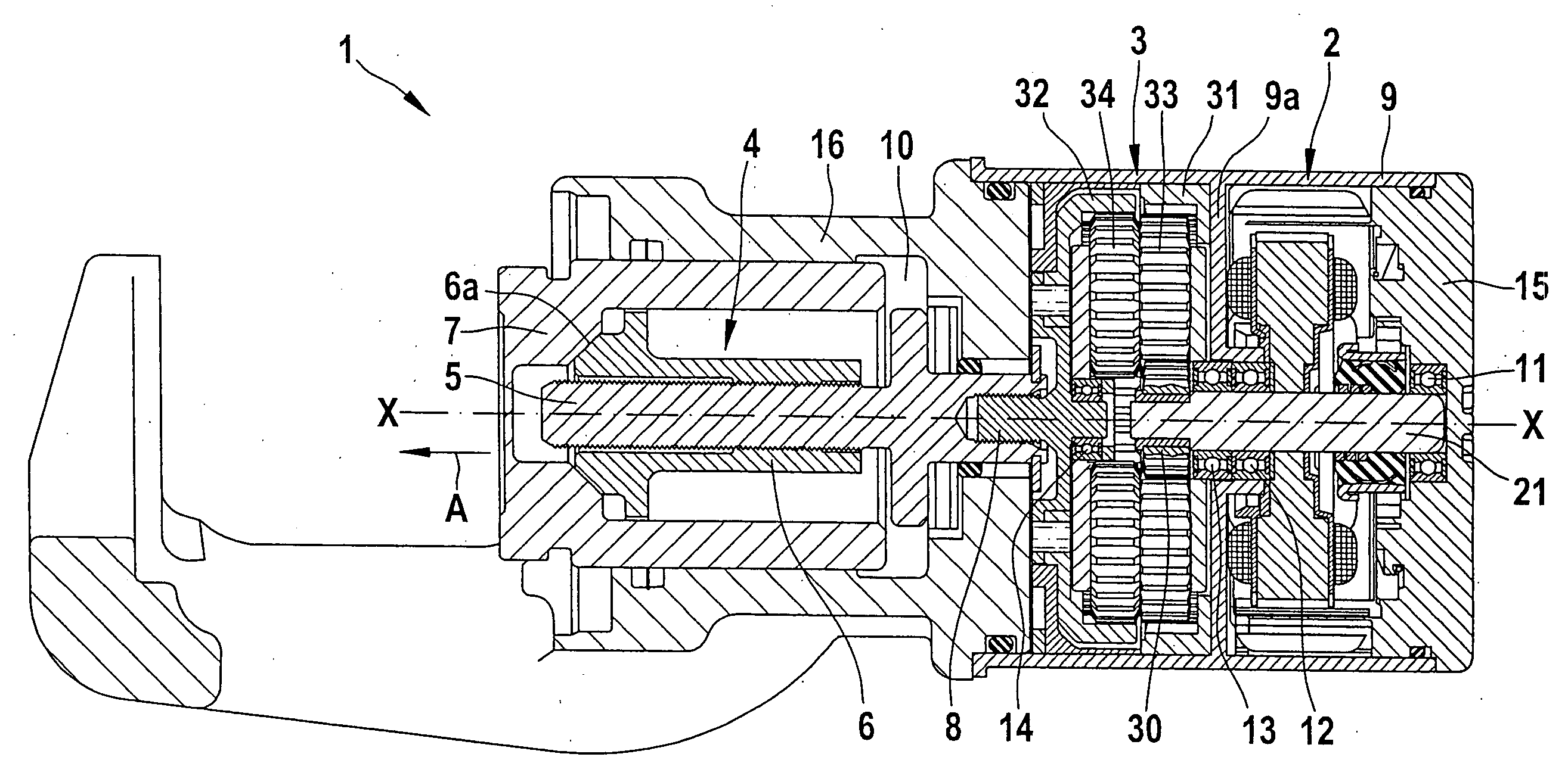
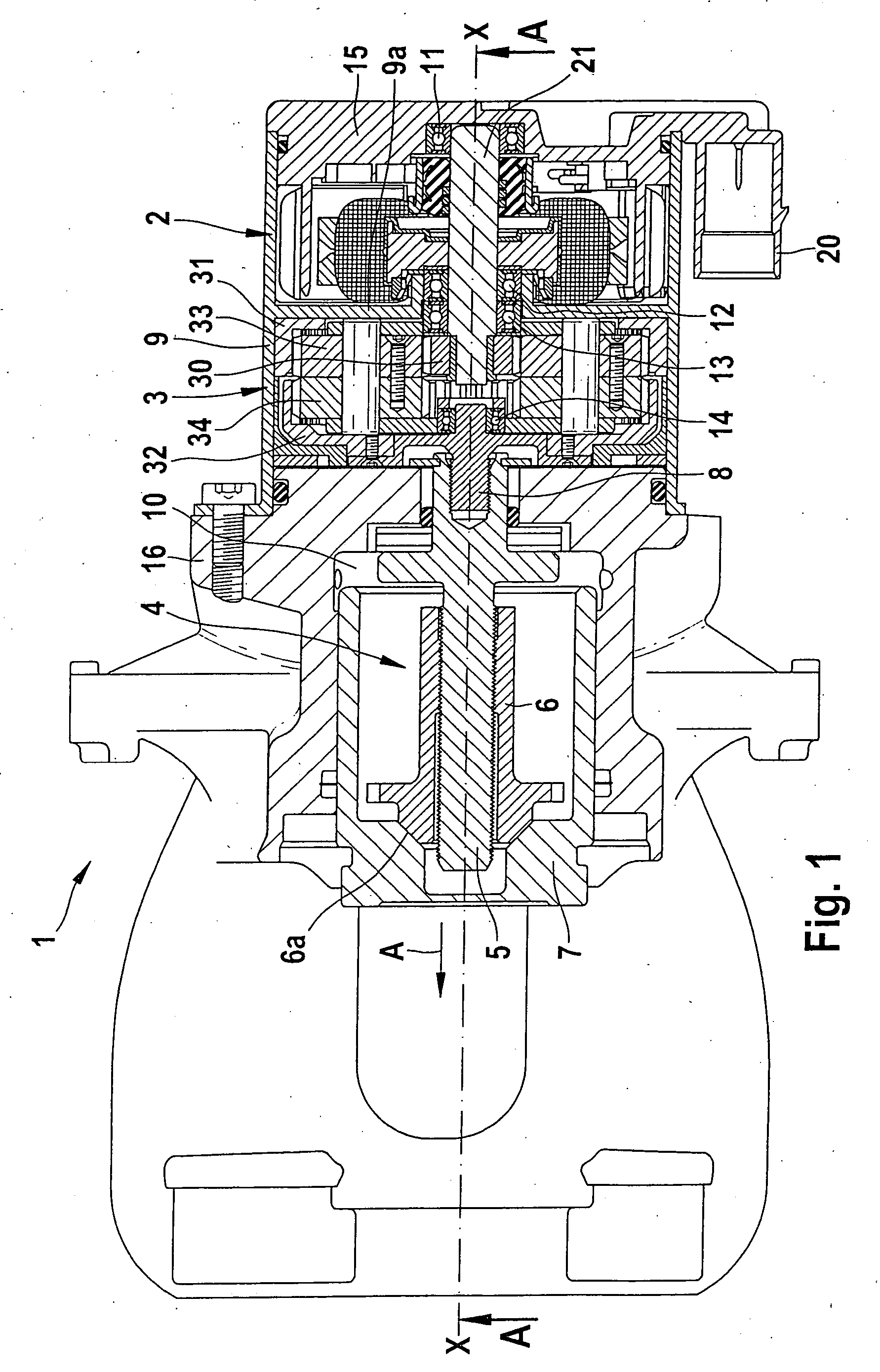
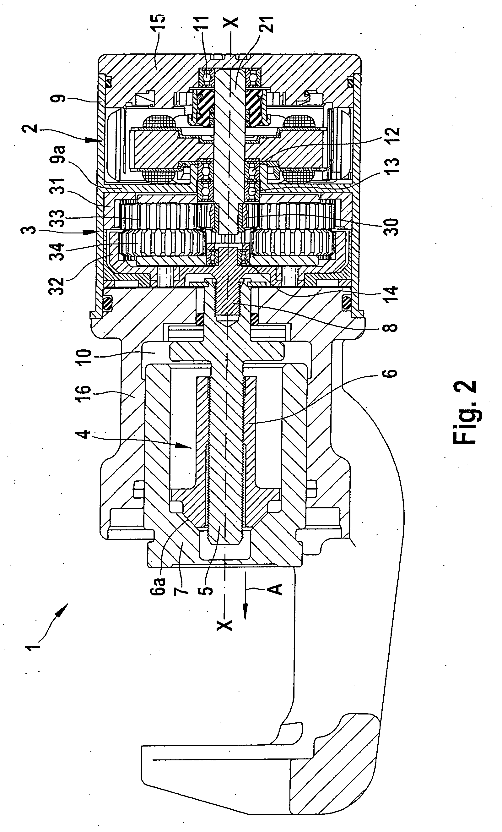
[0033] Functioning as the service brake of a vehicle, the combined service and parking brake apparatus of the invention is operated by means of hydraulics. Pressurized hydraulic fluid is supplied to a fluid chamber 10, which is connected to a hollow inner region of an essentially cup-shaped working piston 7. In the event of a pressure increase in the fluid chamber 10, the operating piston 7 is moved in the direction of the arrow A in order to place brake pads against a brake disc in an intrinsically known fashion.

[0034] The service and parking brake 1 according to the present invention also includes a parking brake part, which essentially includes an electric motor 2, a transmission 3, and a spindle unit 4. The parking brake according to the present invention is a so-called MOC type (motor on caliper), in which a driver request to actuate the parking brake is transmitted by means of an electrical signal to a control unit, which operates the electric motor in order to mechanically e...


PUM


Abstract

A combined service and parking brake apparatus, having a brake unit equipped with a brake disc and at least one brake pad in which a fluid pressure actuatable brake piston is able to place the brake pad against the brake disc and having a parking brake unit which includes an electric drive unit, a transmission, and a spindle unit equipped with a nut and spindle in order to mechanically lock the brake unit in a parking brake position, and in which the electric drive unit, the transmission, and the spindle unit are situated in series on a common axis.

Description

CROSS REFERENCE TO RELATED APPLICATIONS [0001] This application is based on German Patent Application Nos. 20 2005 015 404.0 filed on 29 Sep. 2005 and 10 2005 055 085.1 filed on 18 Nov. 2005, upon which priority is claimed. BACKGROUND OF THE INVENTION [0002] 1. Field of the Invention [0003] The invention relates to a combined service and parking brake apparatus for vehicles and a method for executing an emergency braking action by means of the parking brake apparatus in the event of a failure of the service brake of the vehicle. [0004] 2. Description of the Prior Art [0005] A wide variety of combined service and parking brake apparatus designs are known from the prior art. A brake apparatus of this kind includes, for example, a hydraulic service brake and a mechanical parking brake (emergency brake). Recently, parking brakes are no longer mechanically actuated solely by means of a control cable, but are instead actuated by means of an electric motor mounted directly on the wheel bra...

Claims


Application Information

Patent Timeline
IPC IPC(8): F16D55/26F16D65/18
CPCF16D65/18F16D2121/02F16D2121/24F16D2127/06F16D2125/40F16D2125/50F16D2123/00
Inventor CHITTKA, STEFAN
Owner ROBERT BOSCH GMBH
Why Eureka
Try Eureka